Sheet processing apparatus and image forming apparatus

a technology of image forming apparatus and processing apparatus, which is applied in the direction of printing presses, thin material processing, printing, etc., can solve the problems of increasing the shift length, reducing the productivity of the image forming apparatus, and processing apparatus requiring a certain processing tim

Active Publication Date: 2014-03-06
CANON KK
View PDF9 Cites 6 Cited by
  • Summary
  • Abstract
  • Description
  • Claims
  • Application Information

AI Technical Summary

Problems solved by technology

Such sheet processing apparatus requires a certain processing time in implementing the binding process on the sheets.
In such a case, although it is necessary to interrupt an image forming process of a succeeding sheet to complete the binding process of the preceding sheet bundle, productivity of the image forming apparatus drops if the image forming process is interrupted.
Due to that, if the number of sheets to be overlapped increases, the sheet processing apparatus described above has a possibility of increasing the shift length between the sheets, of increasing a sheet overlapping length more than a predetermined sheet overlapping length preset to be able to align the sheets in discharging to the processing tray, and of thus causing misalignment.

Method used


Image

  • Sheet processing apparatus and image forming apparatus
  • Sheet processing apparatus and image forming apparatus
  • Sheet processing apparatus and image forming apparatus

Examples


first embodiment

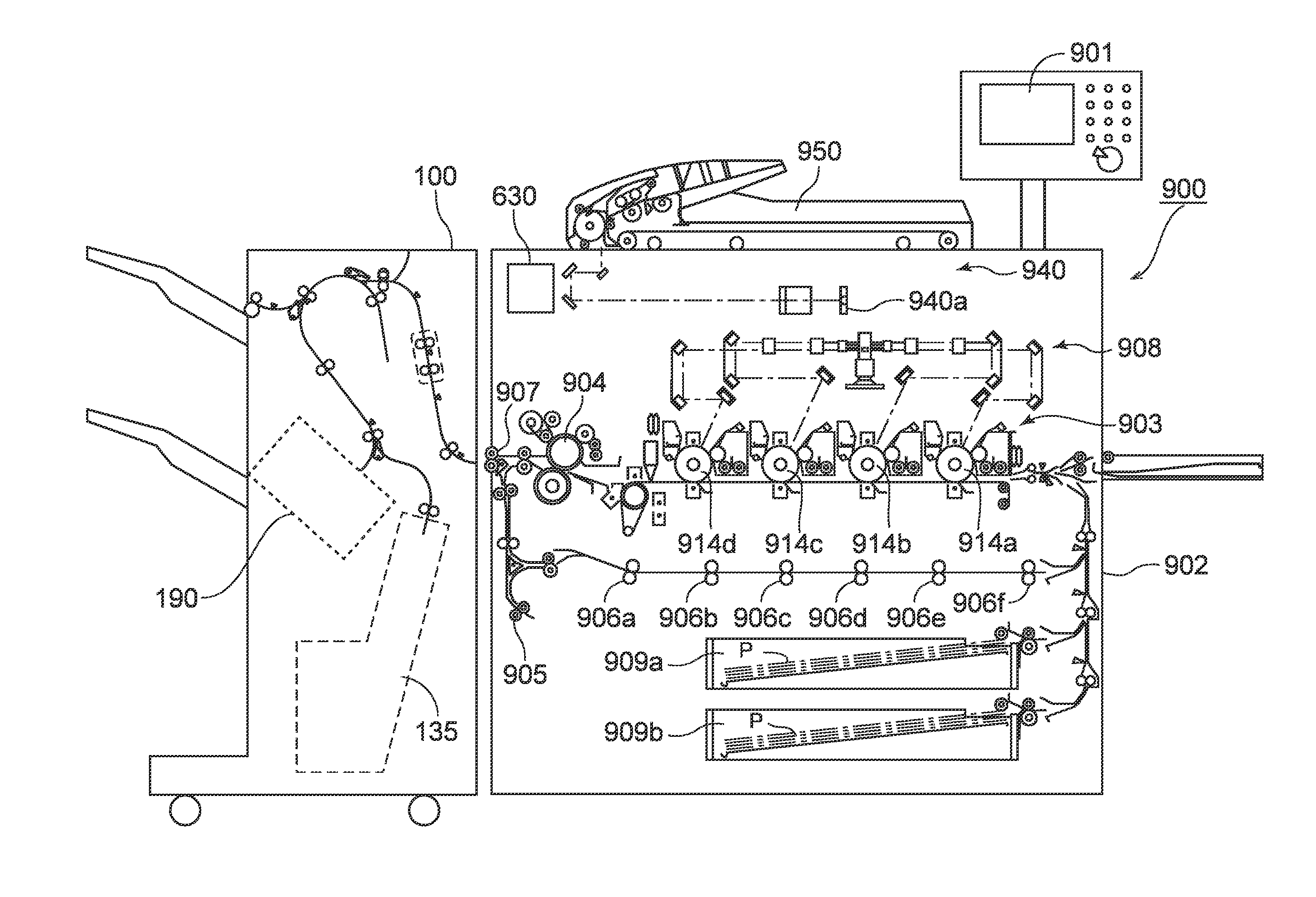
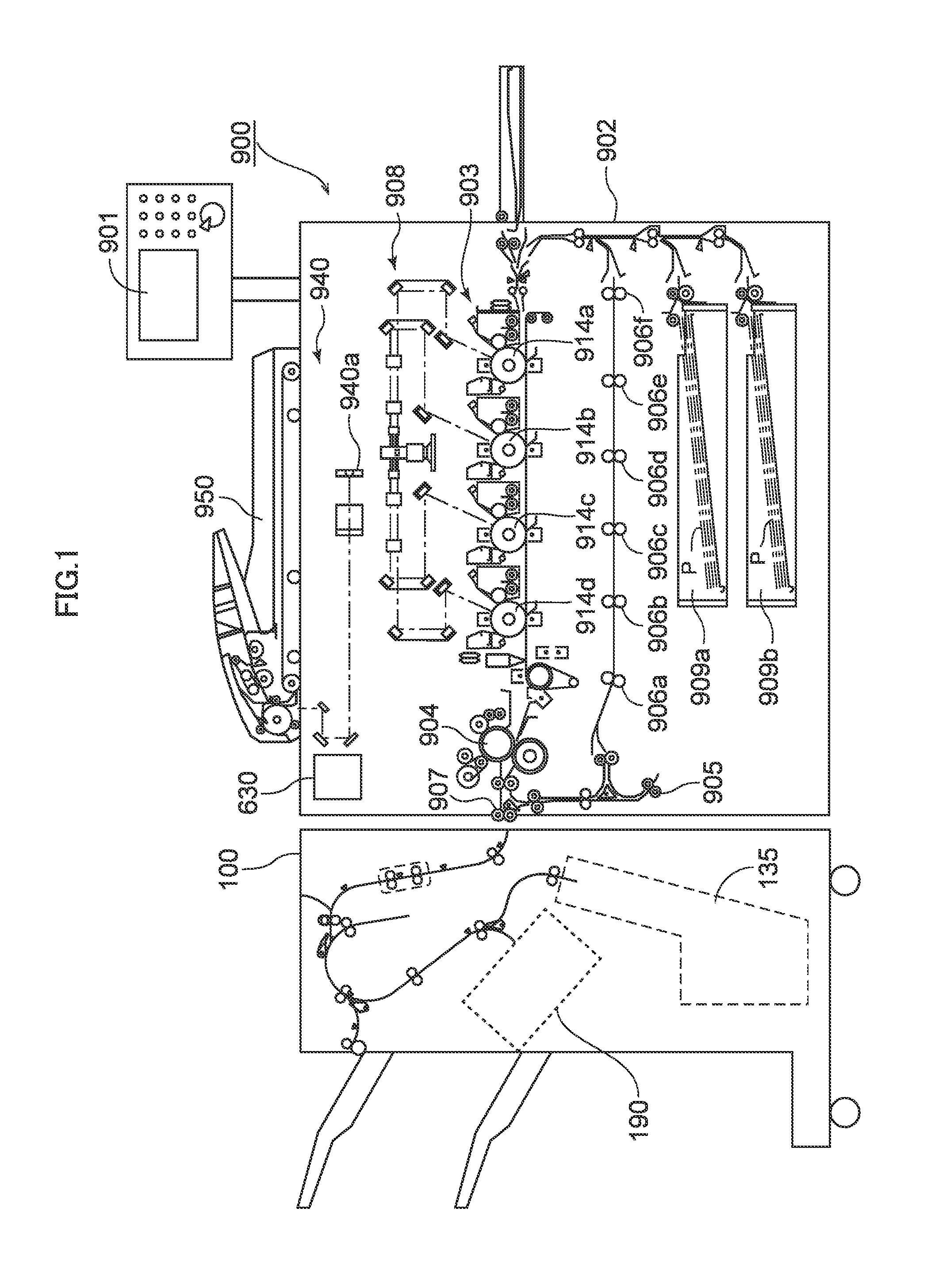
[0036]A first embodiment of the present invention will be described below in detail with reference to the drawings. FIG. 1 is a schematic diagram showing an overall configuration of a color copier including a sheet processing apparatus of the first embodiment. As shown in FIG. 1, the color copier 900, i.e., one exemplary image forming apparatus, includes a body of the color copier (referred to as a ‘copier body’ hereinafter) 902, a document reading portion (image reader) 940 provided at an upper part of the copier body 902, and a document feeder 950 configured to feed documents sequentially to the document reading portion 940 for automatically reading the documents.

[0037]The copier body 902 includes a sheet feeding cassettes 909a and 909b that stack normal sheets P on which images are formed, an image forming portion 903 configured to form toner images on the sheet by using electro-photographic processes, a fixing portion 904 configured to fix the toner image formed on the sheet, an...

second embodiment

[0101]Next, a second embodiment of the invention will be described. It is noted that while the time for starting to normally drive the second buffer roller pair 206 has been set such that the shift length is substantially equalized to (X−(N−n−1)×x in the first embodiment, the second embodiment is different from the first embodiment in that driving speed (sheet conveying speed) of the second buffer roller pair 206 is set such that the shift length is substantially equalized to (X−(N−n−1)×x. Accordingly, only parts different from the first embodiment will be described in the following explanation and a description of common or corresponding parts will be omitted here.

[0102]FIG. 15 is a flowchart illustrating a sheet overlapping process and operation of the present embodiment, and the sheet overlapping process of the present embodiment will be explained below with reference to FIG. 15. When the sheet overlapping process of overlapping sheets is started, the finisher control portion 636...


PUM

PropertyMeasurementUnit
lengthaaaaaaaaaa
rotational speedaaaaaaaaaa
conveying speedaaaaaaaaaa

Abstract

First and second buffer roller pairs are driven such that a sheet conveyed sequentially by a conveying roller pair is overlapped with a standby sheet by shifting in a sheet conveying direction and such that the overlapped sheets standby at a branch path. A shift length in overlapping the standby sheet with the conveyed sheet is set such that the more the number of times of drawal into the branch path of the sheet, the shorter the shift length becomes. Thereby, the shift length between the respective sheets turns out to be a predetermined shift length in overlapping the standby sheets with a final conveyed sheet and conveying the sheets to an intermediate processing tray.

Description

BACKGROUND OF THE INVENTION[0001]1. Field of the Invention[0002]The present invention relates to a sheet processing apparatus configured to implement a process on a sheet, and to an image forming apparatus.[0003]2. Description of the Related Art[0004]Hitherto, some image forming apparatuses, e.g., a copier, a laser printer, a facsimile, and a multi-function copier include a sheet processing apparatus configured to implement various processes such as binding (stapling) and sorting sheets on which image have been formed. One sheet processing apparatus widely used among such sheet processing apparatuses is provided with an intermediate processing tray therein, forms a bundle of sheets (referred to as a ‘bundle sheet’ hereinafter) by stacking a plurality of sheets on the intermediate processing tray, and implements a binding process on the sheet bundle.[0005]Such sheet processing apparatus requires a certain processing time in implementing the binding process on the sheets. Then, there ...

Claims


Application Information

Patent Timeline
Patent Type & Authority Applications(United States)
IPC IPC(8): B65H39/00
CPCB65H39/00B65H29/125B65H31/3027B65H39/10B65H2220/02B65H2301/4213B65H2301/42194B65H2403/942B65H2511/30B65H2801/27B65H2511/22B65H2220/01
Inventor GAMO, YOHEI
Owner CANON KK
Why Eureka
Try Eureka