
Solar Absorber for Concentrated Solar Power Generation

a solar energy and absorber technology, applied in the field of solar energy devices, can solve the problems of inefficiency and expense, add complexity, and cost to the design, and the conversion efficiency achieved with such systems is limited by the materials and manufacturing processes used

Inactive Publication Date: 2014-03-06
SANTA CLARA UNIVERSITY
View PDF10 Cites 2 Cited by
  • Summary
  • Abstract
  • Description
  • Claims
  • Application Information

AI Technical Summary

Benefits of technology

This is a patent about a new design for a solar absorber used in concentrated solar power (CSP) systems. The absorber has a ceramic blackbody cavity receiver and a ceramic heat exchanger shell, which are fused together to form a single piece. The receiver has grooves on its exterior that create tubes when covered by the heat exchanger shell. The absorber is made of two ceramic materials with high emissivity, and the heat exchanger shell is made of silicon carbide or silicon nitride. The shape of the absorber can be square, rectangular, or hexagonal. This design creates a more efficient absorber that withstands higher temperatures and has better thermal performance.

Problems solved by technology

Such phase change heat exchangers thus use a second step in the heat transfer process that adds complexity, inefficiency and expense to the design.
These types of CSP systems require large areas to achieve sufficient conversion efficiency for the cost of the system.
In addition, the conversion efficiencies which have been achieved with such systems are limited by the materials and manufacturing processes used.
For example, the current solar absorbers in the art use metal components in one form or another, which limits the overall performance that can be achieved.
Common high temperature metals will begin to fail around 1300 K, and these metals have a low thermal conductivity.
Hack uses a volumetric style heat exchanger, which has a non-uniform temperature field and produces inconsistencies such as transient hot spots, and also imposes heat losses on the working fluid.

Method used


Image

  • Solar Absorber for Concentrated Solar Power Generation
  • Solar Absorber for Concentrated Solar Power Generation
  • Solar Absorber for Concentrated Solar Power Generation

Examples


Embodiment Construction

[0015]In one embodiment, a scalable, modular, low cost, high efficiency solar absorber is provided for a concentrated solar power system such as a thermal dish-Brayton system or heliostat field system. It has reduced production costs and creates a viable small-scale solar power system for home or neighborhood use by achieving better conversion efficiency through its capability to achieve much higher operating temperatures than current receivers.

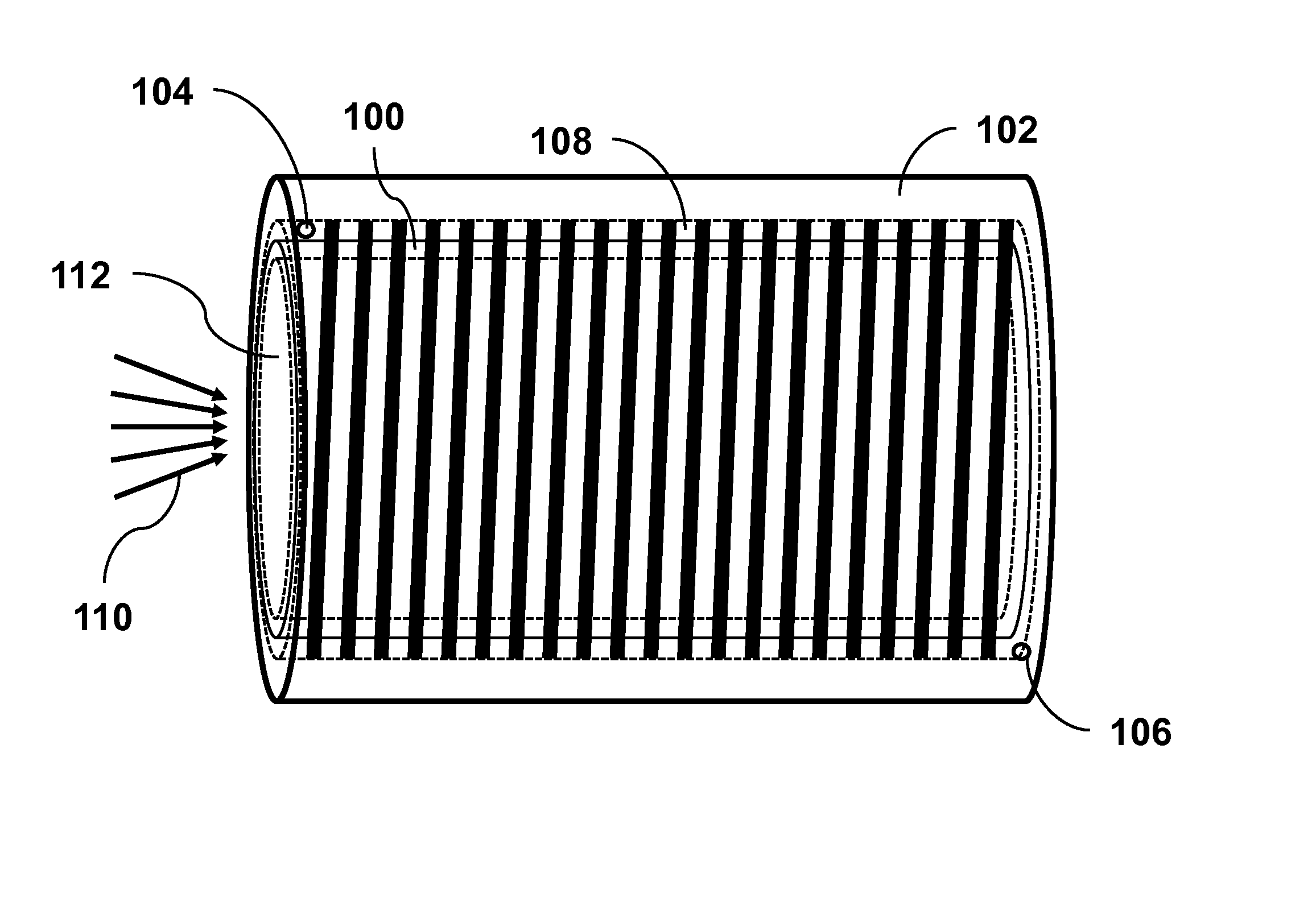
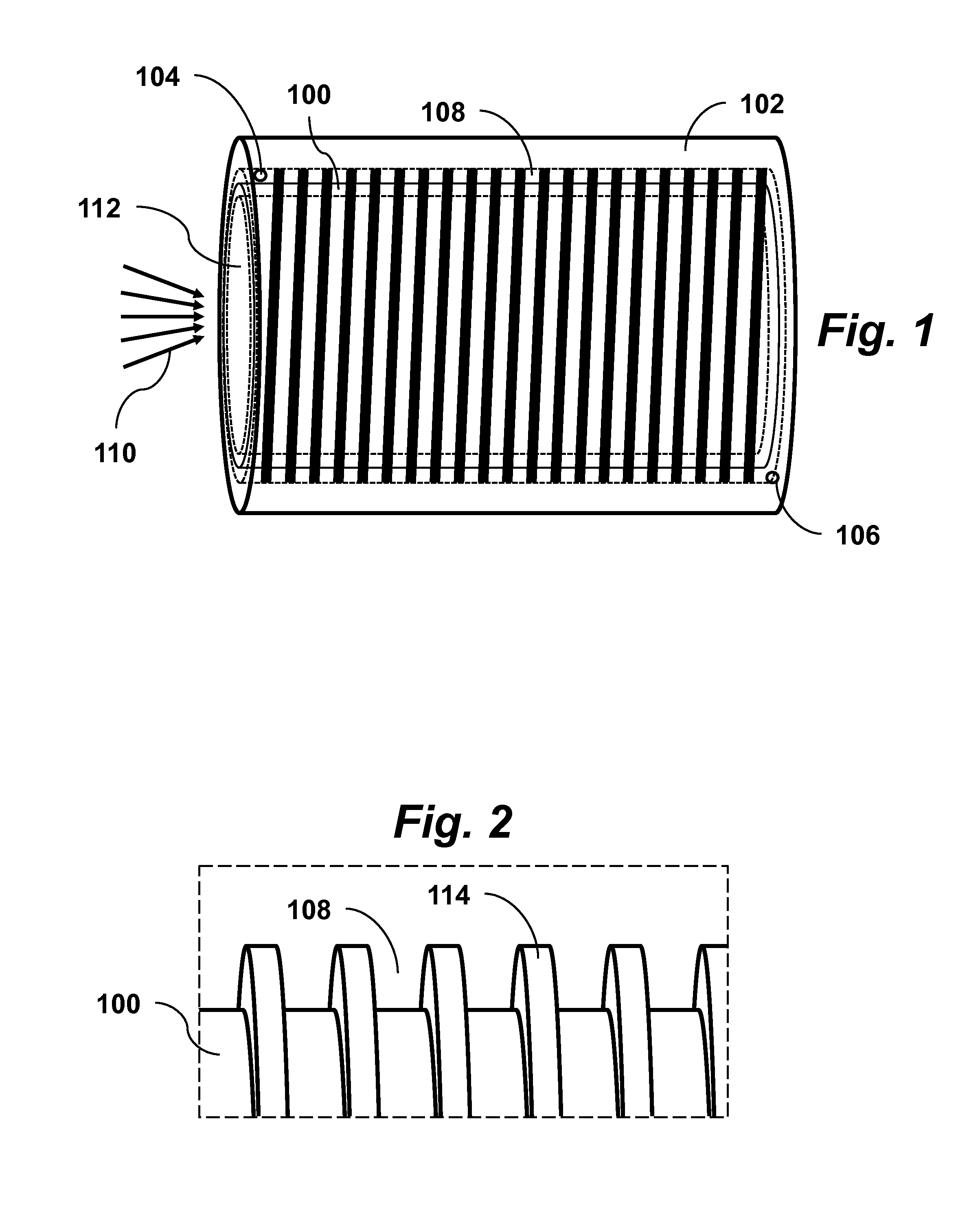
[0016]FIG. 1 shows a schematic drawing of a solar absorber according to an embodiment of the invention. The absorber includes a blackbody radiation receiver 100 and heat exchanger shell 102. An air passage entrance 104 through the shell serves as a cool air inlet and air passage exit 106 serves as hot air outlet. Also shown is the helical air passage duct 108 around the solar cavity receiver 100. This embodiment of the invention uses a cylindrical shaped blackbody cavity 112 of the receiver 100 to absorb incident solar radiation 110 at a temp...


PUM


Abstract

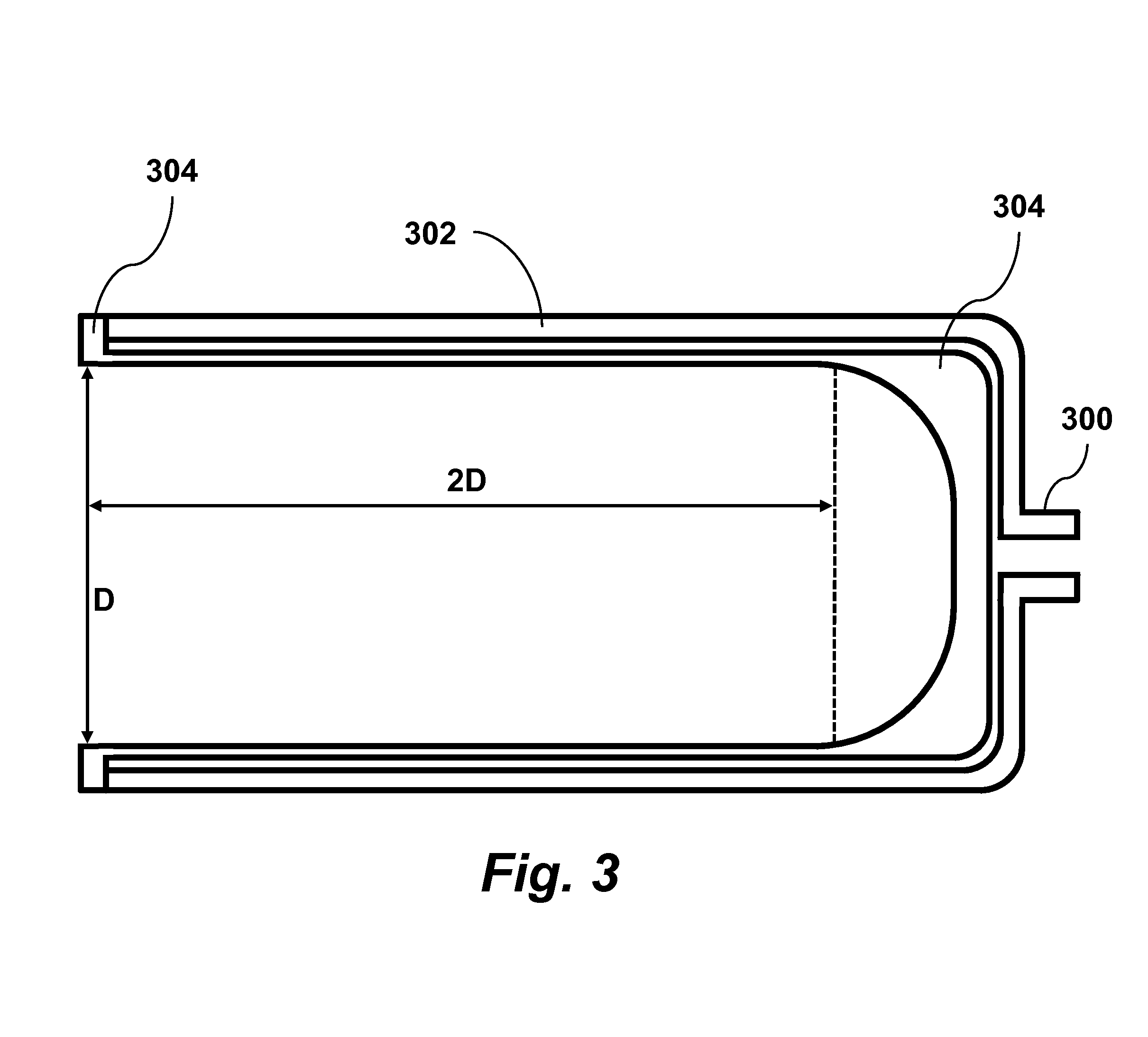
A solar absorber for a concentrated solar power (CSP) system includes a cylindrically shaped blackbody cavity receiver fused to a cylindrically shaped heat exchanger shell covering the receiver to form a monolithic cavity receiver and heat exchanger. An exterior surface of the cavity receiver has grooves embedded to create a duct spiraling about the exterior of the cavity receiver so that the duct forms tubes of a tube-style heat exchanger when covered by the heat exchanger shell. An interior diameter of the cavity receiver is greater than or equal to a diameter of an aperture of the cavity receiver, and a longitudinal interior depth of the cavity is greater than or equal to twice the interior diameter of the cavity receiver. The monolithic solar absorber is preferably composed of a ceramic material such as silicon carbide having emissivity greater than 0.9.

Description

CROSS-REFERENCE TO RELATED APPLICATIONS[0001]This application is a continuation-in-part of U.S. patent application Ser. No. 13 / 789214 filed Mar. 7, 2013, which claims priority from U.S. Provisional Patent Application 61 / 607747 filed Mar. 7,2012, both of which are incorporated herein by reference.STATEMENT OF GOVERNMENT SPONSORED SUPPORT[0002]This invention was made with Government support under contract SU-83603201 awarded by Environmental Protection Agency. The Government has certain rights in this invention.FIELD OF THE INVENTION[0003]The present invention relates generally to solar energy devices. More particularly, the invention relates to solar absorbers for concentrated solar power (CSP) systems.BACKGROUND OF THE INVENTION[0004]Concentrated solar power (CSP) technology seeks to replace fossil fuels in mechanical compression cycles for power generation. Two common types of CSP systems are dish systems and heliostat field systems. A conventional CSP dish system is described, for...

Claims


Application Information

Patent Timeline
IPC IPC(8): F24J2/24F24J2/26F24S10/70F24S10/75
CPCF24J2/266F24J2/242F24S10/72F24S10/754F24S20/20F24S70/16Y02E10/44Y02E10/40
Inventor LEE, HOHYUNNEBER, MATTHEW
Owner SANTA CLARA UNIVERSITY
Learn More