
Thermoelectric energy storage system

Inactive Publication Date: 2014-03-06
ABB RES LTD
View PDF7 Cites 75 Cited by
  • Summary
  • Abstract
  • Description
  • Claims
  • Application Information

AI Technical Summary

Benefits of technology

The present disclosure provides a system and method for storing and retrieving electrical energy using thermoelectric energy storage. This is done by transferring thermal energy to a thermal storage in a charging cycle and generating electricity by retrieving the thermal energy in a discharging cycle. The system includes a working fluid circuit and a thermal storage conduit to circulate a working fluid and transfer heat between a thermal storage medium and a working fluid, which is in a mixed vapor and liquid phase due to its composition. This results in continuous heat transfer and a continuous increase or decrease in temperature of the working fluid during the heat transfer process. The technical effects of this invention include efficient energy storage and utilization, reduced energy wastage, and improved flexibility and reliability of energy utilization.

Problems solved by technology

Base load generators such as nuclear power plants and generators with stochastic, intermittent energy sources, such as wind turbines and solar panels, may generate excess electrical power during times of low power demand.
However, it may be important that all electric energy storage technologies inherently have a limited round-trip efficiency due to thermodynamic limitations.
The rest of the electrical energy is lost.
The efficiency of a thermoelectric storage system is limited for various reasons rooted in the second law of thermodynamics.
Firstly, the conversion of heat to mechanical work in a heat engine is limited due to the Carnot efficiency.
Secondly, the coefficient of performance of any heat pump declines with increased difference between input and output temperature levels.
Thirdly, any heat flow from a working fluid to a thermal storage and vice versa requires a temperature difference in order to happen.
This fact inevitably degrades the temperature level and thus the capability of the heat to do work.
The transfer of heat over large temperature differences is a thermodynamic irreversibility factor.
This means that the larger the temperature differences between the working fluid and the thermal storage medium in the heat exchangers are, the lower the round-trip efficiency will be.
However, these solutions may result in high costs and may generally not be practical.
In such an application, any increase of heat exchange temperature losses during charging and discharging may directly translate into a loss of useful work and reduction of the round trip efficiency of the system.
Ice is an excellent thermal storage medium but ice storage systems have to use heat exchangers which have to grow ice on the heat transfer surfaces (low heat transfer efficiency) or have to limit ice formation per heat exchanger pass (large flow rates) to prevent clogging.
Another disadvantage of known ice storage systems may be that these systems usually cannot exceed an ice content of 50%, which means that half of the thermal storage is unused, increasing both the capital cost of the system and also its footprint.
The downside is that due to its high back-work ratio, a Brayton cycle thermoelectric storage system may suffer from increased losses in the heat pump expansion and heat engine compression steps compared to other thermoelectric storage system designs.
These losses can be counteracted by pushing the operating temperatures of the cold side and hot side of the cycles respectively to very low and very high values, which in turn may make it necessary to store the sensible heat to solid materials such as rocks or sand via special purpose contraptions eventually losing the potential benefit of sensible heat storage through a known fluid-to-fluid heat exchanger.
Thus, it may be problematic to apply the optimization principles of a refrigerator system or a heat engine system to a thermoelectric storage system, because the optimization of the one cycle may degrade the efficiency of the other cycle.
A major hurdle in achieving high efficiencies in thermoelectric storage system operation may be large temperature differences between the hot side and cold side in heat exchangers.
Minimizing temperature differences in heat exchangers may become especially challenging when latent heat storage systems are used and the heat transfer involves conduction through the solid phase of the storage material which might be the case with the above mentioned transcritical thermoelectric storage system.

Method used


Image

  • Thermoelectric energy storage system
  • Thermoelectric energy storage system
  • Thermoelectric energy storage system

Examples


Embodiment Construction

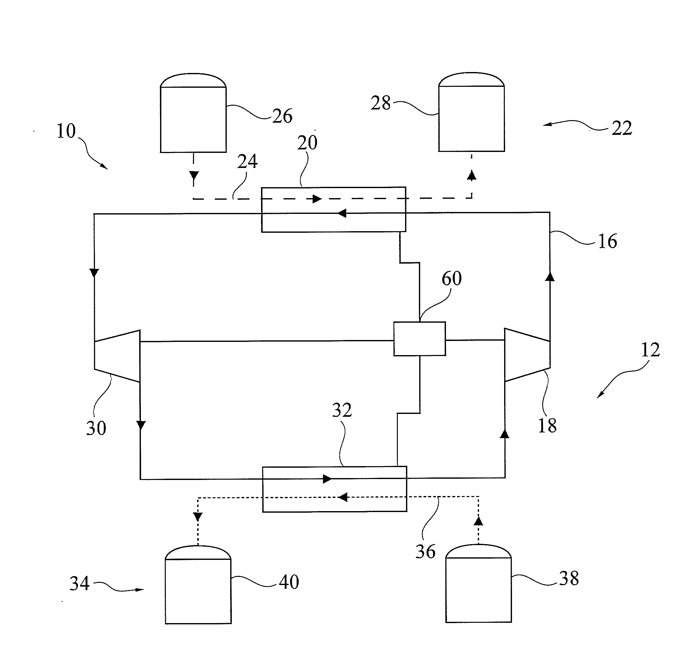
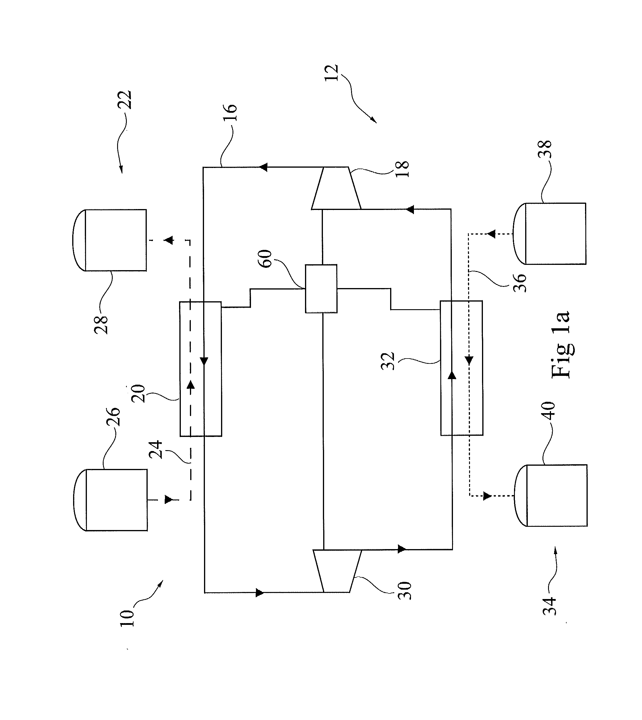
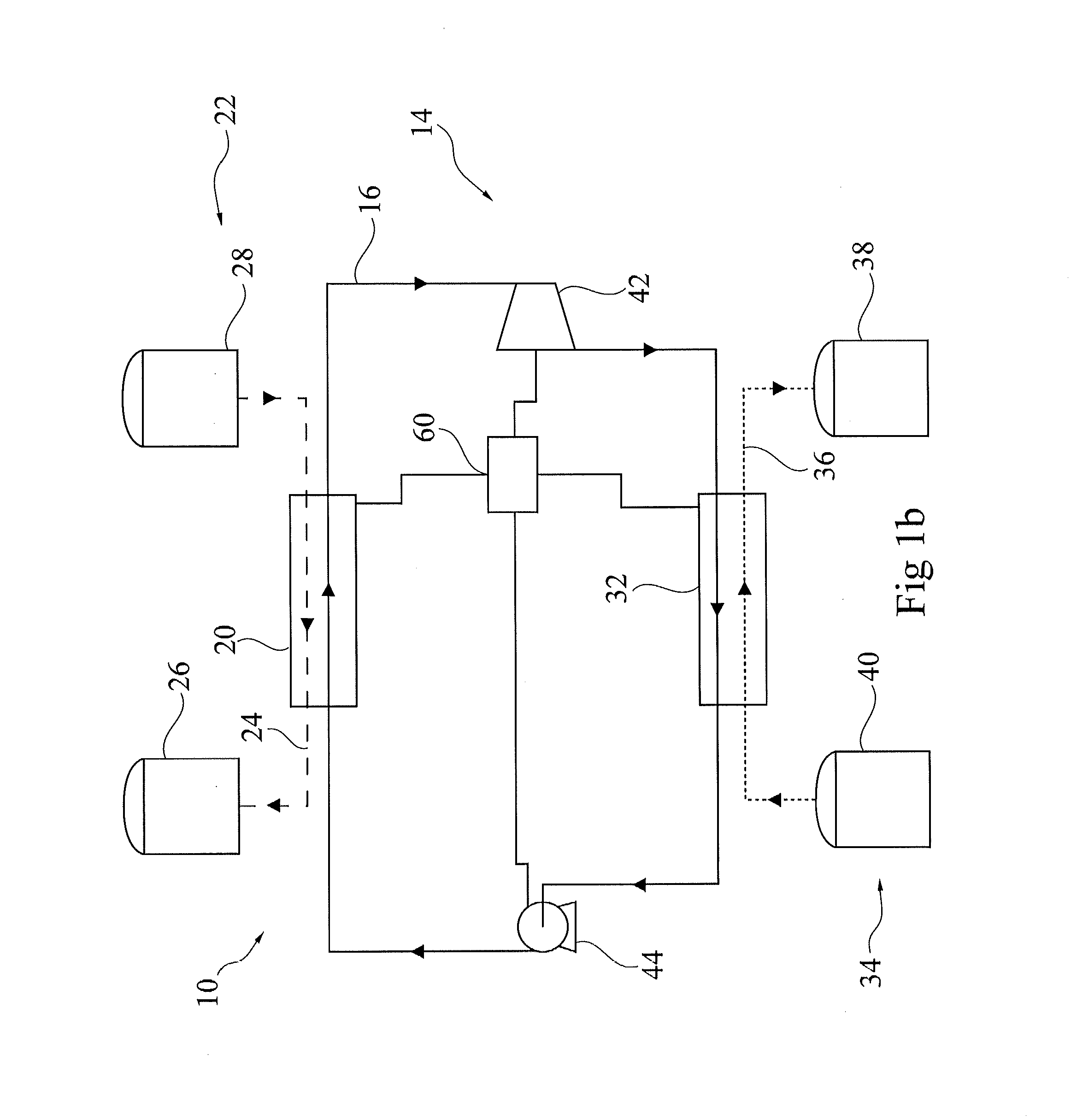
[0030]Exemplary embodiments of the present disclosure provide an efficient thermoelectric energy storage having a high round-trip efficiency and a minimal approach temperature, while minimizing the amount of required thermal storage medium, and also minimizing the cost.

[0031]An exemplary embodiment of the present disclosure provides a thermoelectric energy storage system for storing electrical energy by transferring thermal energy to a thermal storage in a charging cycle, and for generating electricity by retrieving the thermal energy from the thermal storage in a discharging cycle.

[0032]According to an exemplary embodiment of the present disclosure, the thermoelectric energy storage system includes a working fluid circuit configured to circulate a working fluid through a heat exchanger, and a thermal storage conduit configured to transfer a thermal storage medium from a thermal storage tank through the heat exchanger. The working fluid includes a zeotropic mixture.

[0033]In other wo...


PUM


Abstract

A thermoelectric energy storage system and method are provided for storing electrical energy by transferring thermal energy to a thermal storage in a charging cycle, and for generating electricity by retrieving the thermal energy from the thermal storage in a discharging cycle. The thermoelectric energy storage includes a working fluid circuit configured to circulate a working fluid through a heat exchanger, and a thermal storage conduit configured to transfer a thermal storage medium from a thermal storage tank through the heat exchanger. The working fluid includes a zeotropic mixture. The working fluid is in a mixed vapor and liquid phase and has continuously rising or continuously falling temperature during heat transfer due to the working fluid including the zeotropic mixture.

Description

RELATED APPLICATIONS[0001]This application claims priority as a continuation application under 35 U.S.C. §120 to PCT / EP2011 / 060323, which was filed as an International Application on Jun. 21, 2011 designating the U.S., and which claims priority to European Application 10167030.5 filed in Europe on Jun. 23, 2010. The entire contents of these applications are hereby incorporated by reference in their entireties.FIELD[0002]The present disclosure relates to the storage of electric energy. More particularly, the present disclosure relates to a thermoelectric energy storage system, a method for storing and retrieving electrical energy with a thermoelectric energy storage system, and usage of a zeotropic mixture as a working fluid.BACKGROUND INFORMATION[0003]With thermoelectric storage systems, the useful concept of storing electrical energy is implemented by converting electric energy into thermal energy that may be stored for a required time (charging of the storage). The electric energy...

Claims


Application Information

Patent Timeline
IPC IPC(8): F01K3/12F01K25/06
CPCF01K25/06F01K3/12
Inventor OHLER, CHRISTIANHEMRLE, JAROSLAVMERCANGOEZ, MEHMET
Owner ABB RES LTD
Learn More