
Portable device maintenance support apparatus, system, and method

Active Publication Date: 2014-02-27
YOKOGAWA ELECTRIC CORP
View PDF5 Cites 33 Cited by
  • Summary
  • Abstract
  • Description
  • Claims
  • Application Information

AI Technical Summary

Benefits of technology

The present invention allows for accurate identification of the protocol of a complicated signal without mistakenly connecting it to a network.

Problems solved by technology

These two protocol communication methods are basically different and mutually conflicting.
If there is fluctuation in the DC loop voltage, the judgment is made that a problem has occurred in the process loop, or that the occurrence of a problem is imminent.
These errors are associated with specific process apparatuses or receiver nodes in the process control loop.
If an incorrect connection is made between a terminal and a network, not only is a communication connection not made with the field device, but, in the worst case, the field device could be damaged.

Method used


Image

  • Portable device maintenance support apparatus, system, and method
  • Portable device maintenance support apparatus, system, and method
  • Portable device maintenance support apparatus, system, and method

Examples


first embodiment

[0047]First, the present invention will be described.

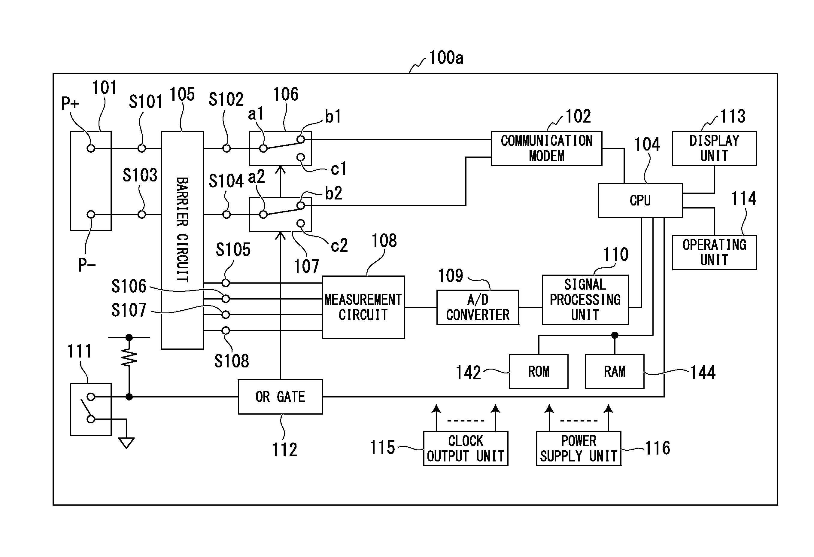
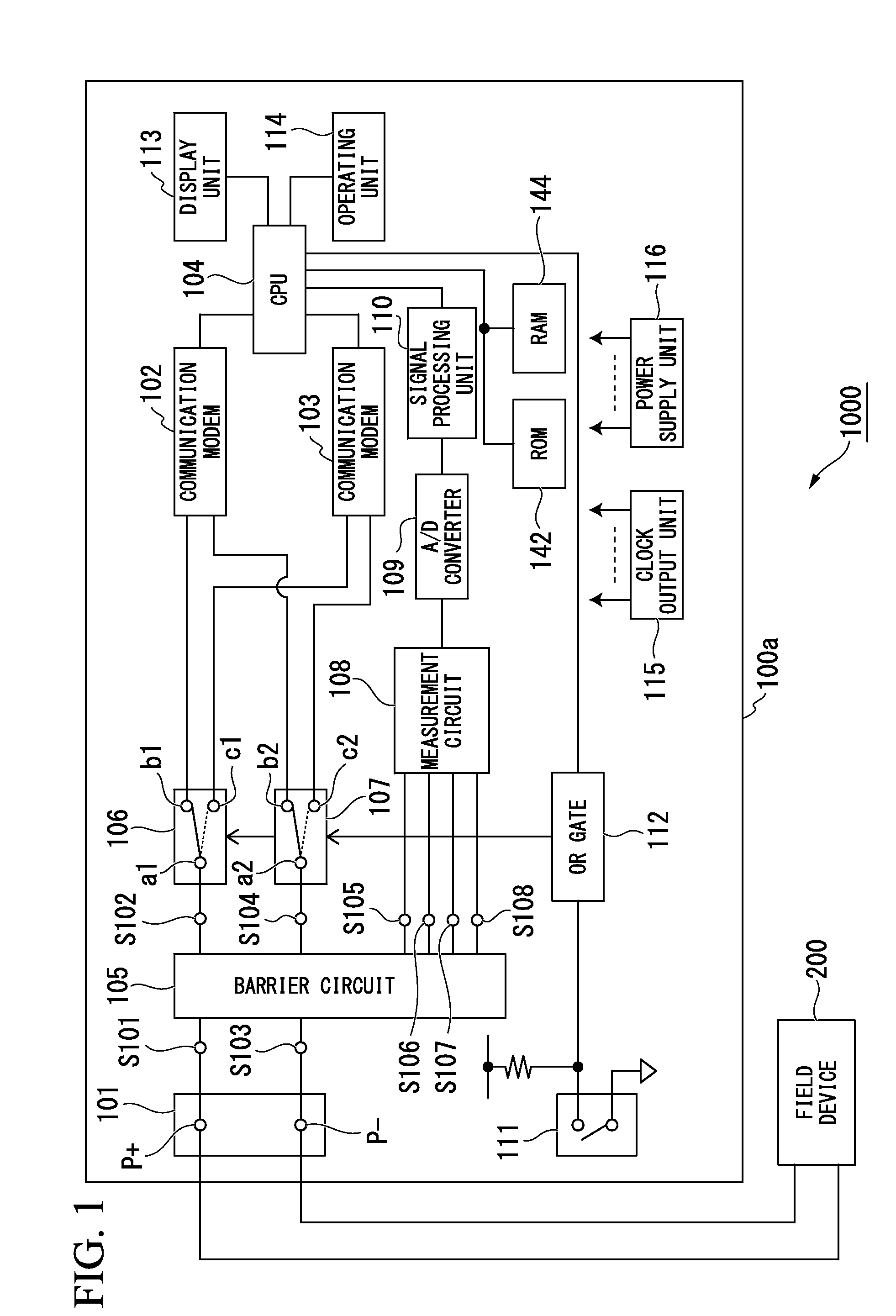
[0048]FIG. 1 shows the constitution of a portable device maintenance support system 1000 according to the first embodiment of the present invention. The portable device maintenance support system 1000 has a portable device maintenance support apparatus 100a and a field device 200.

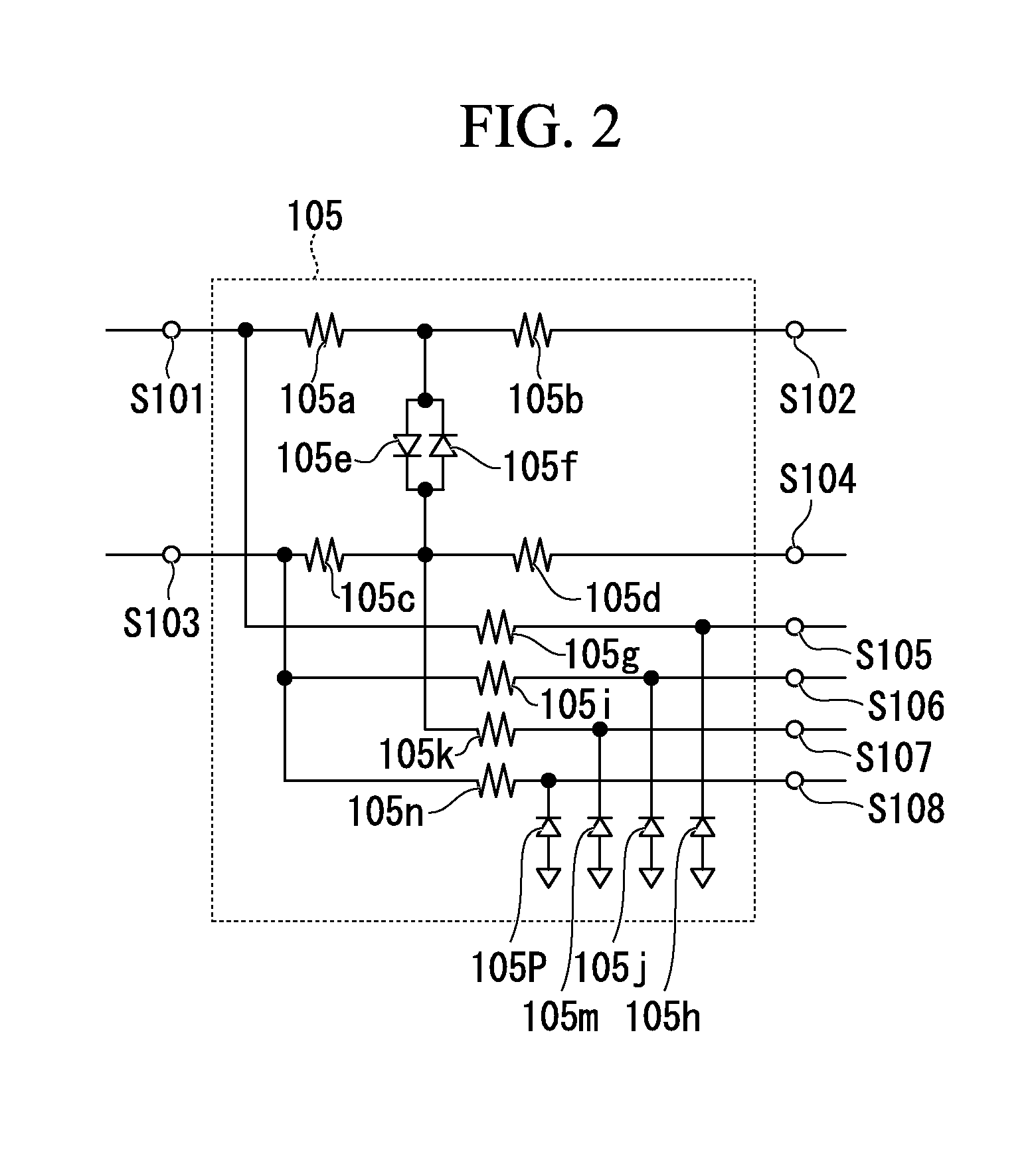
[0049]The portable device maintenance support apparatus 100a has a terminal block 101, connection terminals S101 to S108, communication modems 102 and 103, a CPU 104, a barrier circuit 105, selectors 106 and 107, a measurement circuit 108, an A / D converter 109, a signal processing unit 110, a manual switch 111, an OR gate 112, a display unit 113, an operating unit 114, a clock output unit 115, a power supply unit 116, a ROM 142, and a RAM 144.

[0050]In FIG. 1, the terminal block 101 is for connection to a communication network, and has a positive terminal P+ and a negative terminal P−. The terminal block 101 is used in common for communication networks of ...

second embodiment

[0103]Next, the present invention will be described.

[0104]FIG. 6 shows the constitution of a portable device maintenance support system 2000 according to the second embodiment of the present invention. The portable device maintenance support system 2000 has a portable device maintenance support apparatus 100b and a field device 200.

[0105]The portable device maintenance support apparatus 100b has a terminal block 101, connection terminals S101 to S108, communication modems 102 and 103, a CPU 104, an input / output block 120, selectors 106 and 107, a measurement circuit 108, an A / D converter 109, a signal processing unit 110, a manual switch 111, an OR gate 112, a display unit 113, an operating unit 114, a clock output unit 115, a power supply unit 116, a ROM 142, and a RAM 144.

[0106]Constituent elements in the second embodiment that are the same as in the first embodiment are assigned the same reference numerals and the descriptions thereof will be omitted.

[0107]In the portable device ...


PUM


Abstract

A portable device maintenance support apparatus includes one set of terminals configured to connect to a hybrid communication network performed based on any one of a plurality of protocols, by a compound signal in which an analog signal is superimposed with a digital signal including at least device information, the hybrid communication network being performed between the portable device maintenance support apparatus and a field device, the one set of terminals being common to the plurality of protocols.

Description

BACKGROUND OF THE INVENTION[0001]1. Field of Art[0002]The present invention relates to a portable device maintenance support apparatus, system, and method. More specifically, the present invention relates to a portable apparatus, system, and method preferable for maintenance work such as inspection and adjustment of field devices at the installation location thereof.[0003]The present application claims priority based on Japanese Patent Application No. 2012-183090, filed on Aug. 22, 2012, which is included herein by reference.[0004]2. Background Art[0005]FIG. 8 is a system configuration diagram of an example of a conventional instrumentation system 50. Specifically, FIG. 8 is a system configuration drawing showing an example of an instrumentation system in a control plant such as a petroleum, chemical, steel, paper pulp, gas, LNG, electrical power, water environment, pharmaceuticals.[0006]In FIG. 8, field devices 1 such as temperature transmitters, flow gauges, pressure transmitters,...

Claims


Application Information

Patent Timeline
IPC IPC(8): H04L29/06H04L69/40H04B3/46H04L12/28
CPCH04L69/18G05B19/4185G05B23/0213G05B2219/25151G05B2219/31129G05B2219/36159Y02P90/02
Inventor NAKAMURA, MASAFUMIISHIKAWA, IKUHIKO
Owner YOKOGAWA ELECTRIC CORP
Learn More