
Light-emitting device, vehicle headlamp and illuminaton apparatus

a technology of illumination apparatus and light-emitting device, which is applied in the direction of lighting and heating apparatus, fixed installation, instruments, etc., can solve problems such as loss of illumination ligh

Active Publication Date: 2014-02-27
SHARP FUKUYAMA LASER CO LTD
View PDF1 Cites 10 Cited by
  • Summary
  • Abstract
  • Description
  • Claims
  • Application Information

AI Technical Summary

Benefits of technology

The present invention provides a light-emitting device, a vehicle headlamp, and an illumination apparatus that can efficiently produce a clear edge on the light-emitting section, meaning it can create a sharp edge on the surface it is projected onto.

Problems solved by technology

As a result, there is a problem in that there is a loss of illumination light.

Method used


Image

  • Light-emitting device, vehicle headlamp and illuminaton apparatus
  • Light-emitting device, vehicle headlamp and illuminaton apparatus
  • Light-emitting device, vehicle headlamp and illuminaton apparatus

Examples


Embodiment Construction

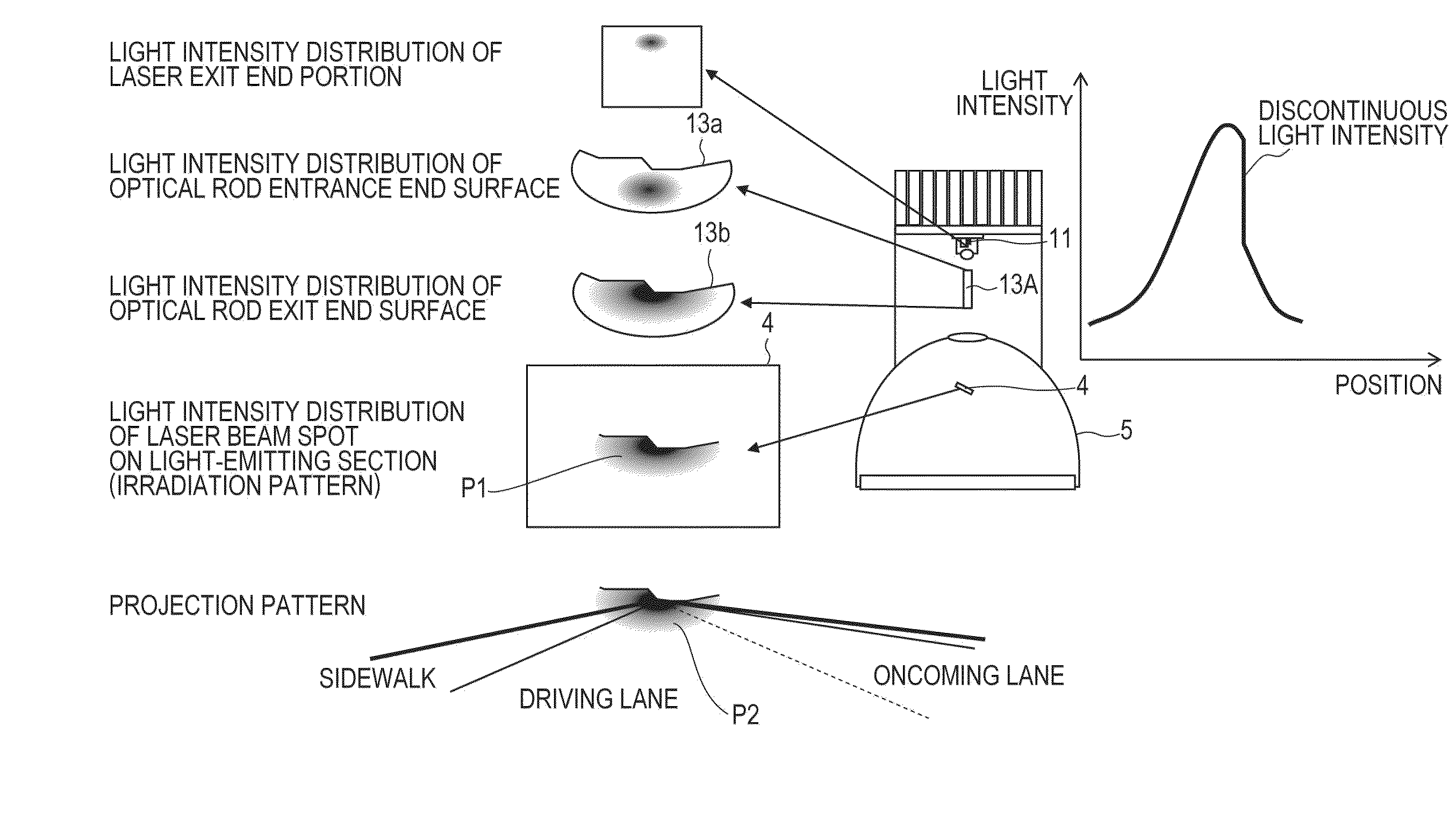
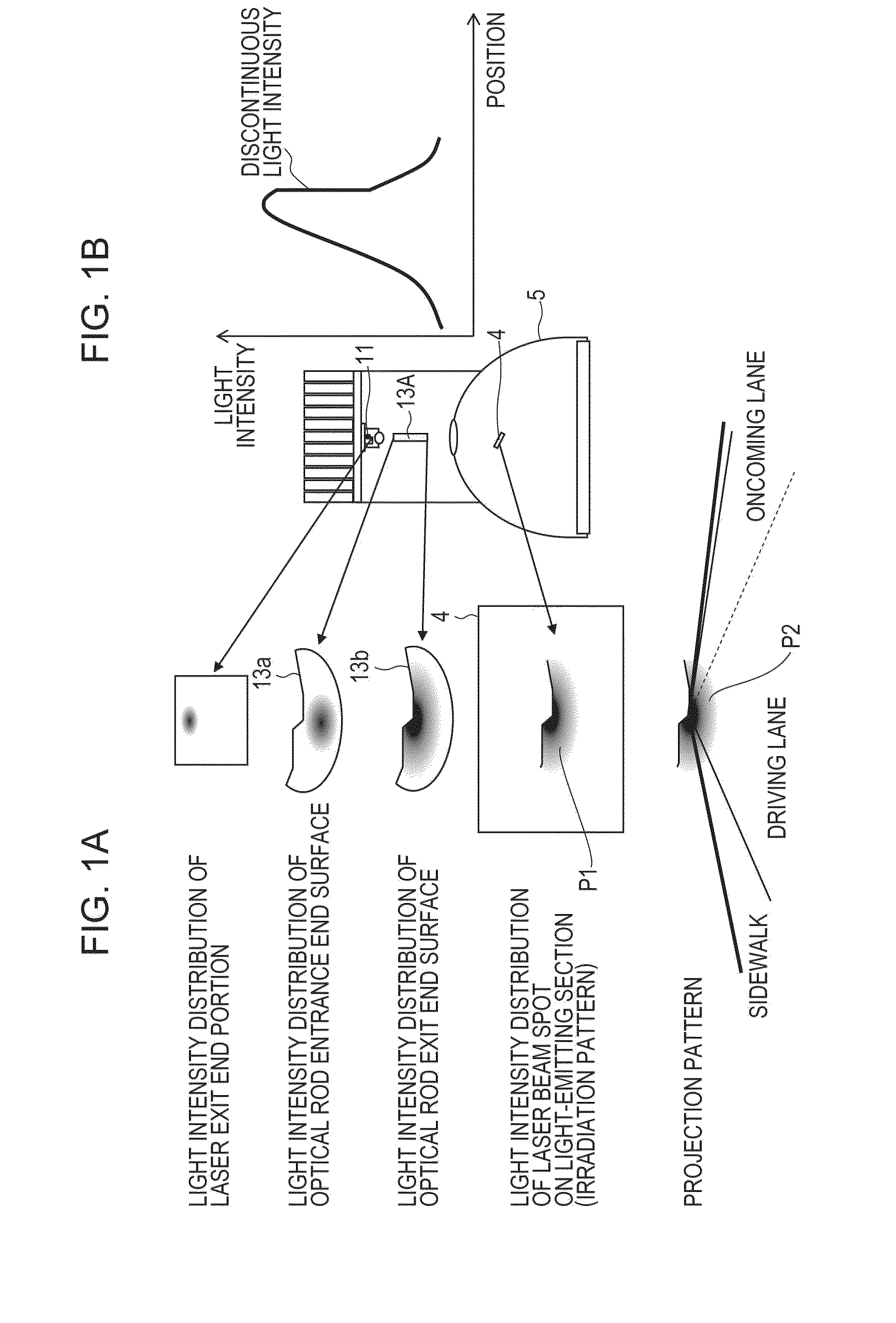
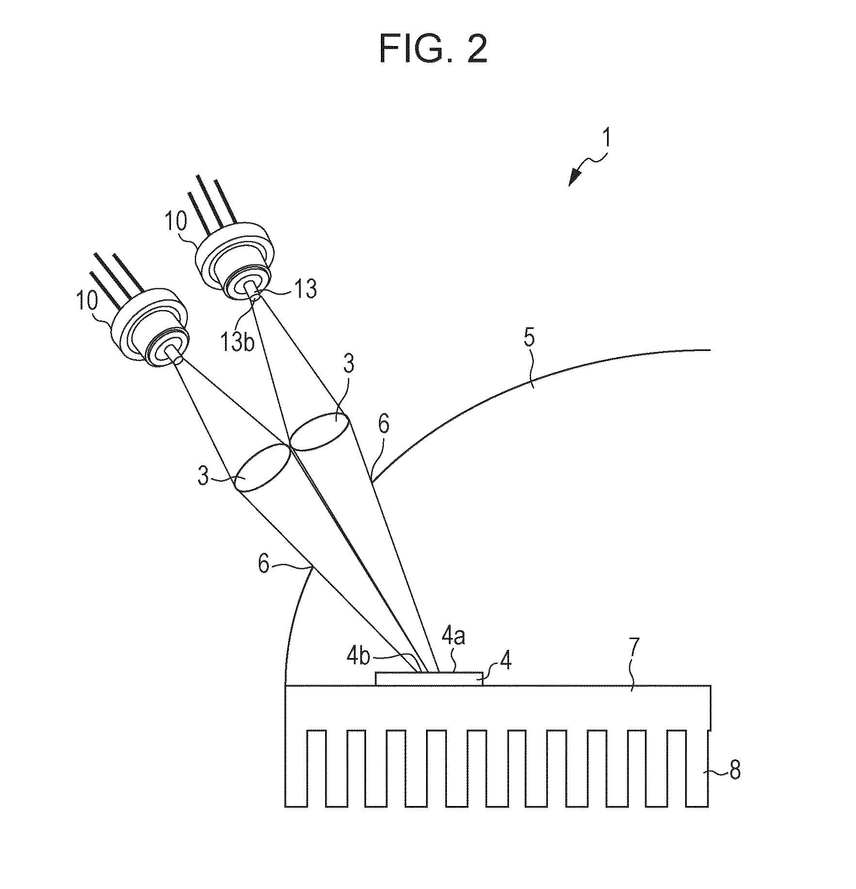
[0077]Below, an embodiment of the present technology will be described in detail with reference to FIG. 1A to FIG. 14C.

[0078]In the present embodiment, description will be given using the headlamp, which serves as the vehicle headlamp which satisfies the light distribution characteristics of a headlamp for passing (a low beam) for an automobile provided with the light-emitting device of an embodiment of the present technology, as an example. However, the light-emitting device of an embodiment of the present technology is not necessarily limited thereto. Further, for example, the light-emitting device may also be realized as a driving headlamp (a high beam), or as a headlamp of a vehicle or a moving object other than the automobile (for example, a person, a ship, an airplane, a submarine, a rocket, or the like), or can also be realized as an illumination apparatus for other applications. The examples of such an illumination apparatus for other applications include a search light, a p...


PUM


Abstract

A headlamp includes the laser chip which emits excitation light, a light-emitting section which contains a phosphor, and an optical rod. The excitation light emitted from the laser chip is optically guided by the optical rod, and the light output from the optical rod enters the light-emitting section. An edge is present in the light intensity distribution of the light-emitting section.

Description

REFERENCE TO RELATED APPLICATIONS[0001]This nonprovisional application claims priority under 35U.S.C. §119 on Japanese Patent Application No. 2012-187038 filed on Aug. 27, 2012, the entire contents of which are hereby incorporated by reference.BACKGROUND OF THE INVENTION[0002]1. Field of the Invention[0003]The present invention relates to a light-emitting device, a vehicle headlamp, and an illumination apparatus, each of which radiates illumination light in a desired projection pattern.[0004]2. Description of the Related Art[0005]In recent years, research on light-emitting devices is becoming active, which light-emitting devices each use, as an excitation light source, a semiconductor light-emitting element such as a light-emitting diode (LED) or a laser diode (LD) and use, as illumination light, fluorescent light that a light-emitting section containing a phosphor generates upon irradiation with excitation light emitted from the excitation light source. Such technology is also appl...

Claims


Application Information

Patent Timeline
Patent Type & Authority Applications(United States)
IPC IPC(8): F21V8/00F21S8/10
CPCF21S48/1241G02B6/0003F21S41/16F21S41/176F21S41/24F21S41/285F21S41/321F21S41/323F21S45/47G02B6/0008
Inventor TAKAHIRA, YOSHIYUKITAKAHASHI, KOJIMAEMURA, YOSUKESAKAUE, TOMOHIROTOYOTA, KENSEI
Owner SHARP FUKUYAMA LASER CO LTD
Learn More