
Multi-Circuit Protection Valve for a Compressed-Air Supply Device of a Vehicle, and Method for Operating a Multi-Circuit Protection Valve

Inactive Publication Date: 2014-02-27
KNORR-BREMSE SYST FUER NUTZFAHRZEUGE GMBH
View PDF5 Cites 4 Cited by
  • Summary
  • Abstract
  • Description
  • Claims
  • Application Information

AI Technical Summary

Benefits of technology

[0011]It can furthermore be provided that the first service brake circuit overflow valve has a lower opening pressure than the second service brake circuit overflow valve. In particular in this way, the first service brake circuit can always be filled first before the second service brake circuit can be filled, which again can then allow the opening of the overflow valve via the force generated on the third active face. In this way it can be ensured that the filling of both service brake circuits is completed before the parking brake circuit is filled.
[0012]It can b

Problems solved by technology

Consequently, to close the service brake and open the parking brake, loss-free service pressures are required in the respective function circuits

Method used


Image

  • Multi-Circuit Protection Valve for a Compressed-Air Supply Device of a Vehicle, and Method for Operating a Multi-Circuit Protection Valve
  • Multi-Circuit Protection Valve for a Compressed-Air Supply Device of a Vehicle, and Method for Operating a Multi-Circuit Protection Valve
  • Multi-Circuit Protection Valve for a Compressed-Air Supply Device of a Vehicle, and Method for Operating a Multi-Circuit Protection Valve

Examples


Example

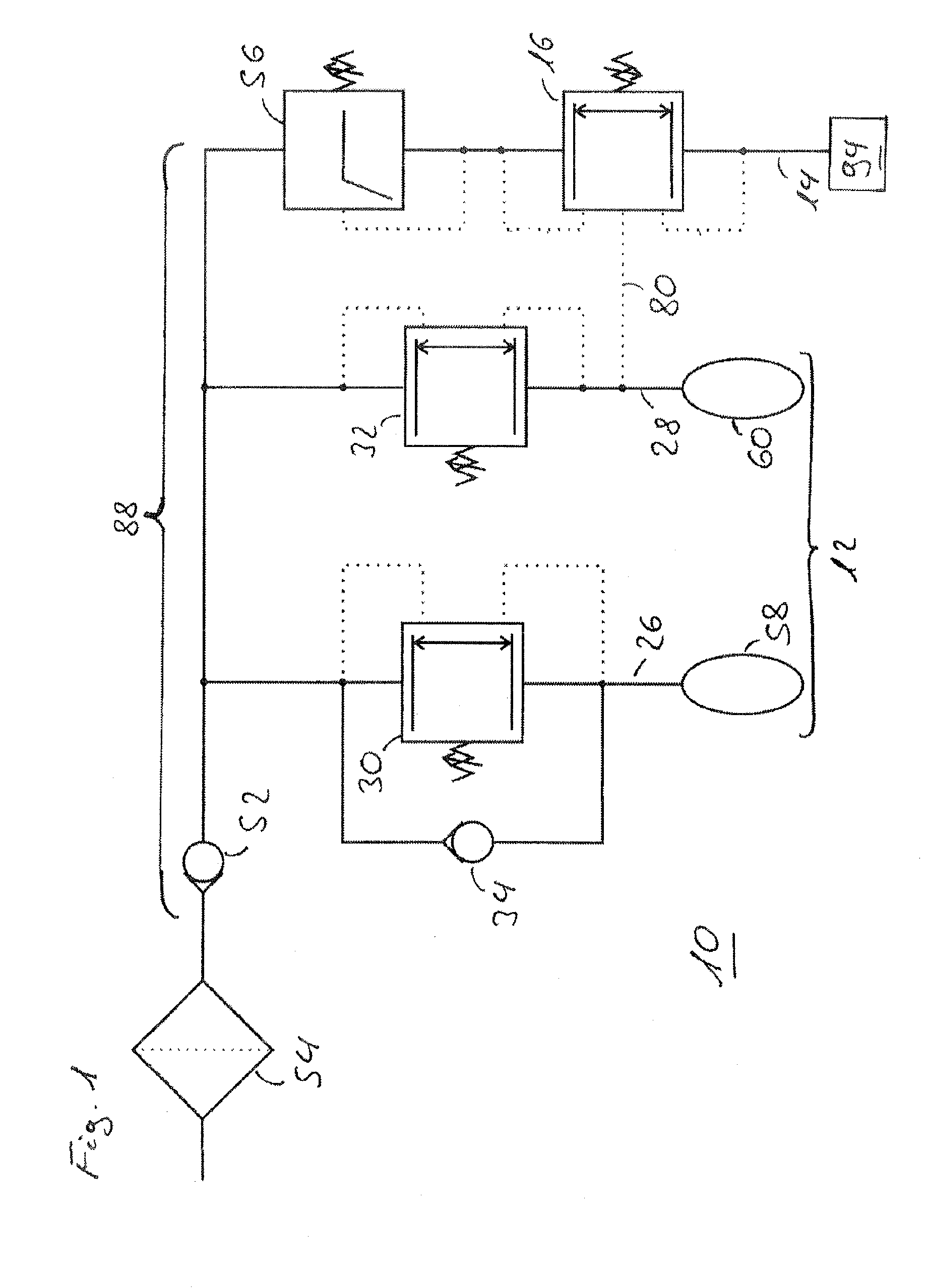
[0030]FIG. 1 shows a first embodiment of a multi-circuit protection valve. The multi-circuit protection valve 10 shown in FIG. 1 has a central line region 88 which is secured against pressure loss on the input side by a central non-return valve 52. Also, the coupling of the central non-return valve 52 with an air dryer 54 of a compressed-air preparation system, which is symbolized by the drying cartridge normally present, is shown on the input side as an example. The central line region 88 branches downstream of the central non-return valve 52 to provide a first port 12 and a second port 14 for compressed-air consumers. Further branches from the central line region 88, which are not shown in FIG. 1, can be provided as required in order to provide further ports, for example, for air suspension, a vehicle trailer, pneumatic transmission control or other ancillary consumers. The first port 12 comprises a first service brake circuit port 26 and a second service brake circuit port 28. Th...

Example

[0032]FIG. 2 shows a second embodiment of a multi-circuit protection valve. In contrast to the embodiment known from FIG. 1, in the embodiment of the multi-circuit protection valve 10 shown in FIG. 2, the parking brake circuit 94 is post-supplied via a supply line 96 from both service brake circuit ports 26, 28. To this end a supply valve 44, which for example can be designed as a “select high” valve, can be coupled to the supply line 96 at a supply valve output port 50. Furthermore, a first supply valve input port 46 is coupled to the first service brake circuit port 26, and a second supply valve input port 48 is coupled to the second service brake circuit port 28. The supply valve 44 can be constructed for example, as shown in FIG. 2, from two simple non-return valves so that the first service brake circuit 58 and the second service brake circuit 60 are secured against each other, and the higher of the two pressures from the two service brake circuits 58, 60 is output at the suppl...

Example

[0035]FIG. 3 shows a third embodiment of a multi-circuit protection valve. The multi-circuit protection valve 10 shown in FIG. 3 differs from the multi-circuit protection valve known from FIG. 1 in particular in the manner in which the control pressure is provided to the overflow valve 16 via the control line 80. According to the embodiment described in FIG. 3, a control valve 36 is proposed which has a first control valve input port 38 and a second control valve input port 40 and a control valve output port 42. The first control valve input port 38 is coupled to the first service brake service circuit port 26 via a first control pressure line 84, while the second control valve input port 40 is coupled to the second service brake circuit port 28 via a second control pressure line 86. The control valve output port 42 is, in turn, connected to the overflow valve 16 via the control line 80. The control valve 36 shown can be designed as a “select low” valve which always outputs at its c...


PUM


Abstract

A multi-circuit protection valve is provided for a vehicle compressed-air supply device. A first port for a service brake includes two mutually separate service brake circuit ports for a first service brake circuit and a second service brake circuit. The two service brake circuit ports are protected by first and second service brake circuit overflow valves, respectively. A second port for a parking brake, is protected by an overflow valve, wherein one of the two service brake circuits can be filled preferentially. The overflow valve has two active surfaces which can be acted on with a valve inlet pressure and a valve outlet pressure, respectively. The overflow valve has a third active surface, which is acted on with the service brake pressure from the non-preferentially filled service brake circuit. Forces generated by the three active surfaces counteract a closing force in order to open or hold open the overflow valve.

Description

BACKGROUND AND SUMMARY OF THE INVENTION[0001]The invention concerns a multi-circuit protection valve for a compressed-air supply device of a vehicle, in particular a truck, with a first port for a service brake, wherein the first port has two separate service brake circuit ports for a first service brake circuit and a second service brake circuit, and wherein the first service brake connection is secured by a first service brake circuit overflow valve and the second service brake circuit port is secured by a second service brake circuit overflow valve, and with a second port for a parking brake which is secured by an overflow valve, wherein the first service brake circuit or the second service brake circuit can be filled as priority, and wherein the overflow valve has a first active face which can be pressurized with a valve input pressure and a second active face which can be pressurized with a valve output pressure.[0002]The invention furthermore concerns a method for operating a ...

Claims


Application Information

Patent Timeline
IPC IPC(8): B60T11/32B60T17/18
CPCB60T17/18B60T11/326B60T17/04B60T17/221B60T11/32
Inventor KAUPERT, OLIVER
Owner KNORR-BREMSE SYST FUER NUTZFAHRZEUGE GMBH
Learn More