
Tool for filling a gearbox with lubricant

Inactive Publication Date: 2010-09-30
VALMONT INDUSTIES INC
View PDF6 Cites 2 Cited by
  • Summary
  • Abstract
  • Description
  • Claims
  • Application Information

AI Technical Summary

Benefits of technology

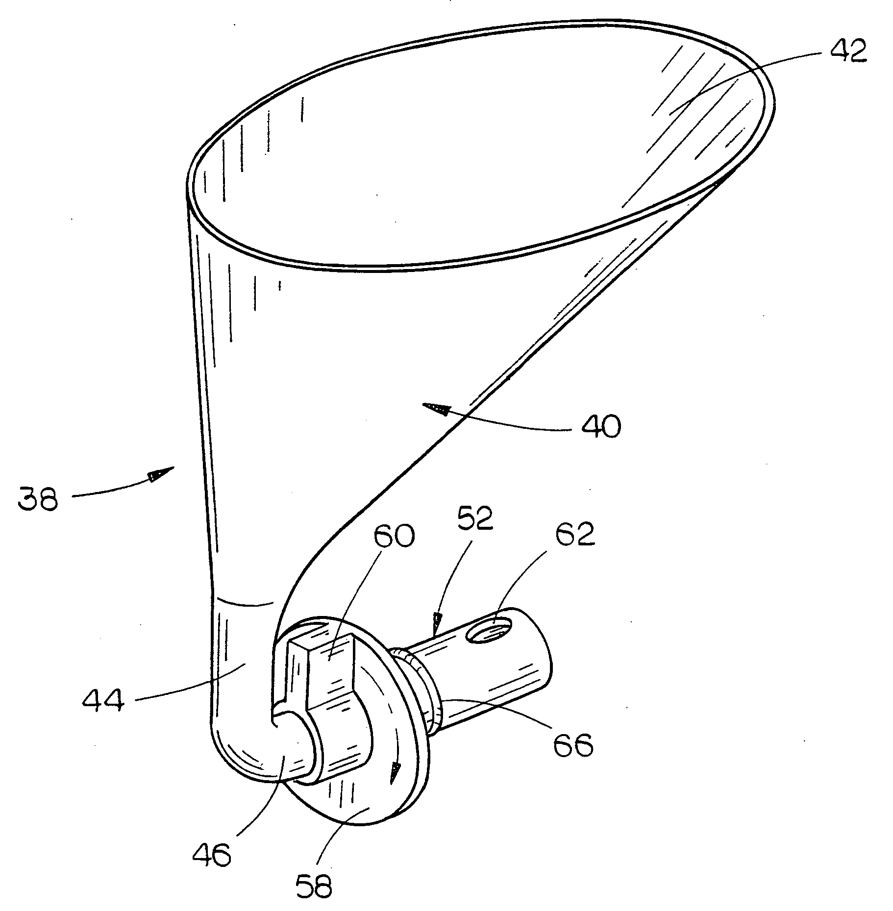
[0007]In the preferred embodiment, the center of the funnel-like member is laterally offset with respect to the first tubular portion so that the tool may be easily used adjacent the tire of the drive unit.
[0008]When the second and third tubular portions are inserted into the fill opening of the gearbox, lubricant is placed into the funnel-like member if lubricant has not been previously placed therein. The third tubular portion is then rotated with respect to the second tubular portion so that the first and second discharge openings in the second and third tubular portions respectively are in register with one another. The design of this invention permits lubricant to only reach the full level and prevents over filling. This is achieved by the location of the first discharge opening. During the filling of the lubricant, the lubricant level will only rise to the bottom of the first discharge opening. At that point, air cannot escape from the gearbox and additional lubricant will not flow into the gearbox, thus preventing over filling. Because the gearbox cannot be over filled with lubricant, the air volume therein will be maintained. Pressure will not be increased and lubricant will not be forced through the seals thereby creating leaks.
[0011]A further object of the invention is to provide a tool for filling a gearbox with lubricant which ensures that the gearbox will not be over filled with lubricant.
[0012]A further object of the invention is to provide a tool for filling a gearbox with lubricant which prevents spillage of the lubricant.

Problems solved by technology

Moreover, this Summary is not intended for use as an aid in determining the scope of the claimed subject matter.

Method used


Image

  • Tool for filling a gearbox with lubricant
  • Tool for filling a gearbox with lubricant
  • Tool for filling a gearbox with lubricant

Examples


Embodiment Construction

[0023]Embodiments are described more fully below with reference to the accompanying figures, which form a part hereof and show, by way of illustration, specific exemplary embodiments. These embodiments are disclosed in sufficient detail to enable those skilled in the art to practice the invention. However, embodiments may be implemented in many different forms and should not be construed as being limited to the embodiments set forth herein. The following detailed description is, therefore, not to be taken in a limiting sense in that the scope of the present invention is defined only by the appended claims.

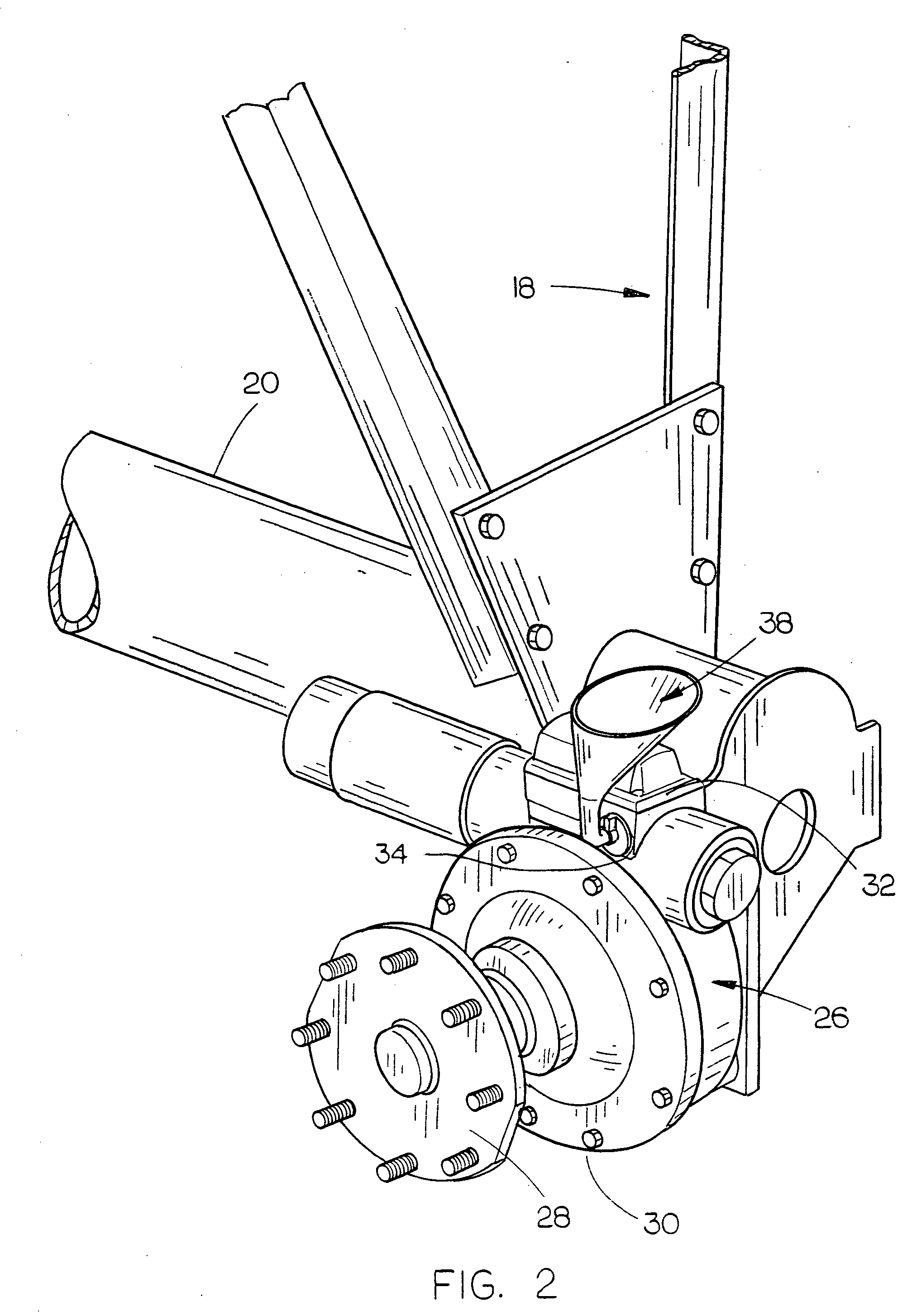
[0024]The numeral 10 refers generally to a mechanized irrigation system such as a center pivot irrigation system. The system 10 conventionally includes a center pivot structure 12 having a main water pipeline 14 extending outwardly therefrom. The pipeline 14 includes a plurality of span structures. Each of the drive units 18 includes a main beam 20 having drive wheels 22 and 24 rot...


PUM


Abstract

A tool is provided for filling a gearbox with lubricant. The tool includes structure which prevents the gearbox from being over filled with lubricant. The tool of this invention enables access to the fill opening of the gearbox and prevents spillage or leakage. The tool is ideally suited for use with a gearbox mounted on the drive unit of a mechanized irrigation system.

Description

BACKGROUND OF THE INVENTION[0001]1. Field of the Invention[0002]This invention relates to a tool for filling a gearbox with lubricant and more particularly to the tool for filling a gearbox, mounted on a drive unit of a mechanized irrigation system, with liquid lubricant.[0003]2. Description of the Related Art[0004]In mechanized irrigation systems such as a center pivot irrigation system, the water pipeline is propelled around a field by a plurality of spaced-apart drive units or towers with each of the drive units having a pair of driven wheels. Normally, a gearbox is associated with each of the drive wheels with the gearboxes being driven by an electric motor or the like. The gearbox is filled with a liquid lubricant and it is extremely important that the lubricant in the gearbox be maintained at the proper level. Prior to the instant invention, the filling of the gearbox with lubricant required the use of long funnels of hoses to direct the flow of lubricant to the fill hole of t...

Claims


Application Information

Patent Timeline
IPC IPC(8): B67C11/04
CPCA01G25/092
Inventor MCGEE, RICKY D.
Owner VALMONT INDUSTIES INC
Learn More