
Facility and method for manufacturing a rotor blade of a wind turbine and method for setting up the facility

Inactive Publication Date: 2014-02-27
SIEMENS AG
View PDF6 Cites 0 Cited by
  • Summary
  • Abstract
  • Description
  • Claims
  • Application Information

AI Technical Summary

Benefits of technology

The patent is about a wind turbine rotor blade manufacturing facility that can be easily set up at the installation site of the wind turbine. The facility is designed to be compact and can be transported to the installation site using a truck or train. This simplifies the process of setting up the facility and reduces costs. The patent also mentions that the components of the facility fit into a standard container size, making transportation easier. Overall, the technical effects of the patent are to provide a compact, easy-to-transport, and cost-effective wind turbine rotor blade manufacturing facility.

Problems solved by technology

Since wind turbines have grown in size considerably involving that also the components from which the wind turbines are assembled have grown in size, transporting of the components to the final installation site may be difficult.
In particular, a rotor blade of a wind turbine may have a length between 30 m and 60 m, in particular around 40 m, which may make transporting the rotor blade to the installation site difficult.
However, this solution may have the major disadvantage that the solution induces a weak joint where the halves are connected upon assembly of the rotor blade.

Method used


Image

  • Facility and method for manufacturing a rotor blade of a wind turbine and method for setting up the facility
  • Facility and method for manufacturing a rotor blade of a wind turbine and method for setting up the facility

Examples


Embodiment Construction

[0037]The illustration in the drawing is in schematic form.

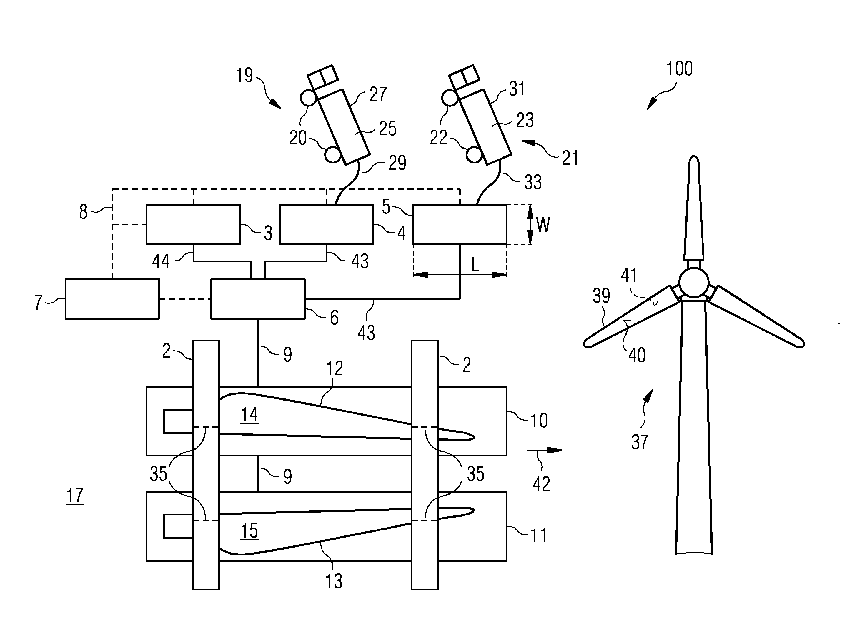
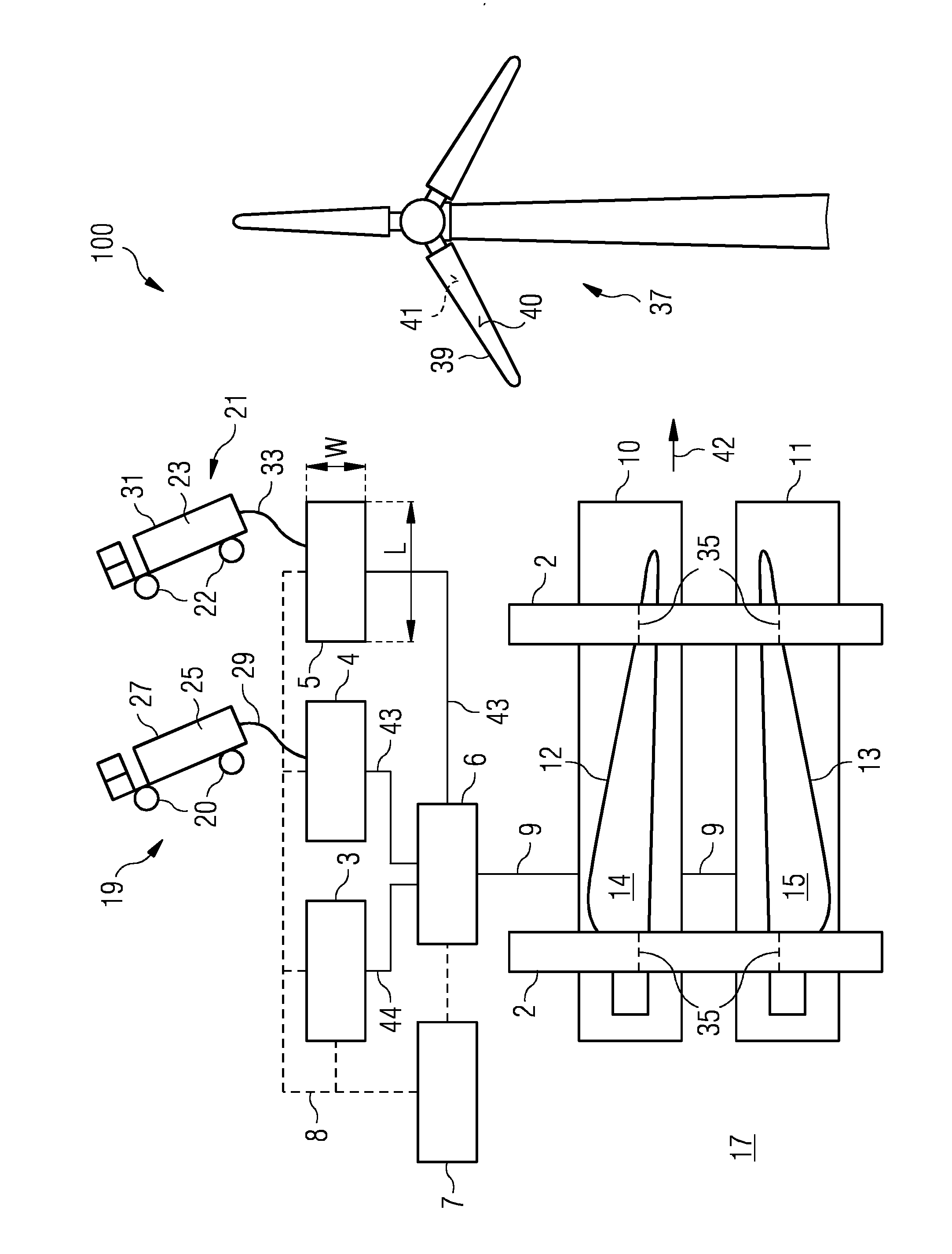
[0038]The figure schematically illustrates a facility 100 for manufacturing a rotor blade 39 of a wind turbine 37 according to an embodiment of the present invention.

[0039]The facility 100 comprises an injection machine 6 for injecting an injection material mixed within the injection machine 6 via a releasable pipe 9 into a mould formed by a first mould portion 10 and a second mould portion 11. The first mould portion provides one half of the mould and the second mould portion 11 represents or provides another half of the mould which may be assembled by positioning the first mould portion 10 and the second mould portion 11 opposite to each other such that a rim 12 of an inner surface 14 of the first mould portion 10 aligns with a rim 13 of an inner surface 15 of the second mould portion 11. The figure does not illustrate the assembled state of the mould formed by the mould portions 10 and 11 but illustrates when the first mo...


PUM

PropertyMeasurementUnit
Electric energyaaaaaaaaaa
Thermosettingaaaaaaaaaa

Abstract

A facility for manufacturing a rotor blade of a wind turbine is provided. The facility includes an injection machine for injecting an injection material into a mould to form the rotor blade, a movable tank system for accommodating precursor material to be supplied to the injection machine for preparing the injection material, wherein the movable tank system has wheels for moving the tank system. Further, a method for setting up a facility and a method for manufacturing a rotor blade are described.

Description

FIELD OF INVENTION[0001]The present invention relates to a facility and to a method for manufacturing a rotor blade of a wind turbine and to a method for setting up a manufacturing facility at a facility site which is in particular close to an installation site of the wind turbine to which the rotor blade is to be mounted.ART BACKGROUND[0002]Wind turbines are nowadays installed at various remote sites onshore or offshore. This requires that components of the wind turbine need to be transported to the final installation site of the wind turbine. Since wind turbines have grown in size considerably involving that also the components from which the wind turbines are assembled have grown in size, transporting of the components to the final installation site may be difficult. In particular, a rotor blade of a wind turbine may have a length between 30 m and 60 m, in particular around 40 m, which may make transporting the rotor blade to the installation site difficult.[0003]Various ways of ...

Claims


Application Information

Patent Timeline
IPC IPC(8): B29C31/04
CPCB29C31/04B29C31/10B29C37/006F03D1/0675Y02E10/72Y02P70/50B29C70/48B29C70/546
Inventor SCHIBSBYE, KARSTEN
Owner SIEMENS AG
Learn More