
Partial block memory operations

a memory operation and partial block technology, applied in the field of partial block memory operations, can solve the problems of large power consumption, parasitic current leakage, current consumption and/or parasitic current leakage when memory operations are performed, and large current consumption and/or parasitic current leakag

Active Publication Date: 2014-02-06
MICRON TECH INC
View PDF9 Cites 64 Cited by
  • Summary
  • Abstract
  • Description
  • Claims
  • Application Information

AI Technical Summary

Benefits of technology

The patent text discusses a problem in memory devices, such as NAND memory, where there is a large amount of power consumption and current leakage when performing memory operations on a block or page basis. This problem is caused because a memory operation may affect a large number of control gates or source select gates in the memory device. The text proposes a solution to reduce the power consumption and current leakage by grouping the pages into smaller units, but this may still require additional power sources to support the extensive current consumption and current leakage. The technical effect of this patent is to provide a solution to reduce the power consumption and current leakage in memory devices, particularly in 3D NAND memory, by organizing the pages into smaller units and optimizing the control signals to minimize the impact on the memory cells.

Problems solved by technology

Accordingly, as the page size becomes larger, the power used during a data line swing or page buffer flip may increase, so that a relatively large amount of power may be consumed when relatively small amounts of data, such as 4 KB, are read, programmed, erased or verified.
Thus, as the size of the memory block or page increases, so does the current consumption and / or parasitic current leakage when memory operations are performed.
Thus, the memory block or page upon which the memory operation is performed may cause extensive current consumption and / or parasitic current leakage.
This, in turn, may incur the need to supply the memory device with additional and / or alternative power sources to support the extensive current consumption and / or parasitic leakage.

Method used


Image

  • Partial block memory operations
  • Partial block memory operations
  • Partial block memory operations

Examples


Embodiment Construction

[0045]The description that follows includes illustrative apparatuses (circuitry, devices, structures, systems, and the like) and methods (e.g., processes, protocols, sequences, techniques, and technologies) that embody the inventive subject matter. In the following description, for purposes of explanation, numerous specific details are set forth in order to provide an understanding of various embodiments of the inventive subject matter. It will be evident, however, to those of ordinary skill in the art, that various embodiments of the inventive subject matter may be practiced without these specific details. Further, well-known apparatuses and methods have not been shown in detail so as not to obscure the description of various embodiments.

[0046]As used herein, the term “or” may be construed in an inclusive or exclusive sense. Additionally, although various embodiments discussed below may primarily focus on multi-level cell memory devices, the embodiments are merely given for clarity...


PUM


Abstract

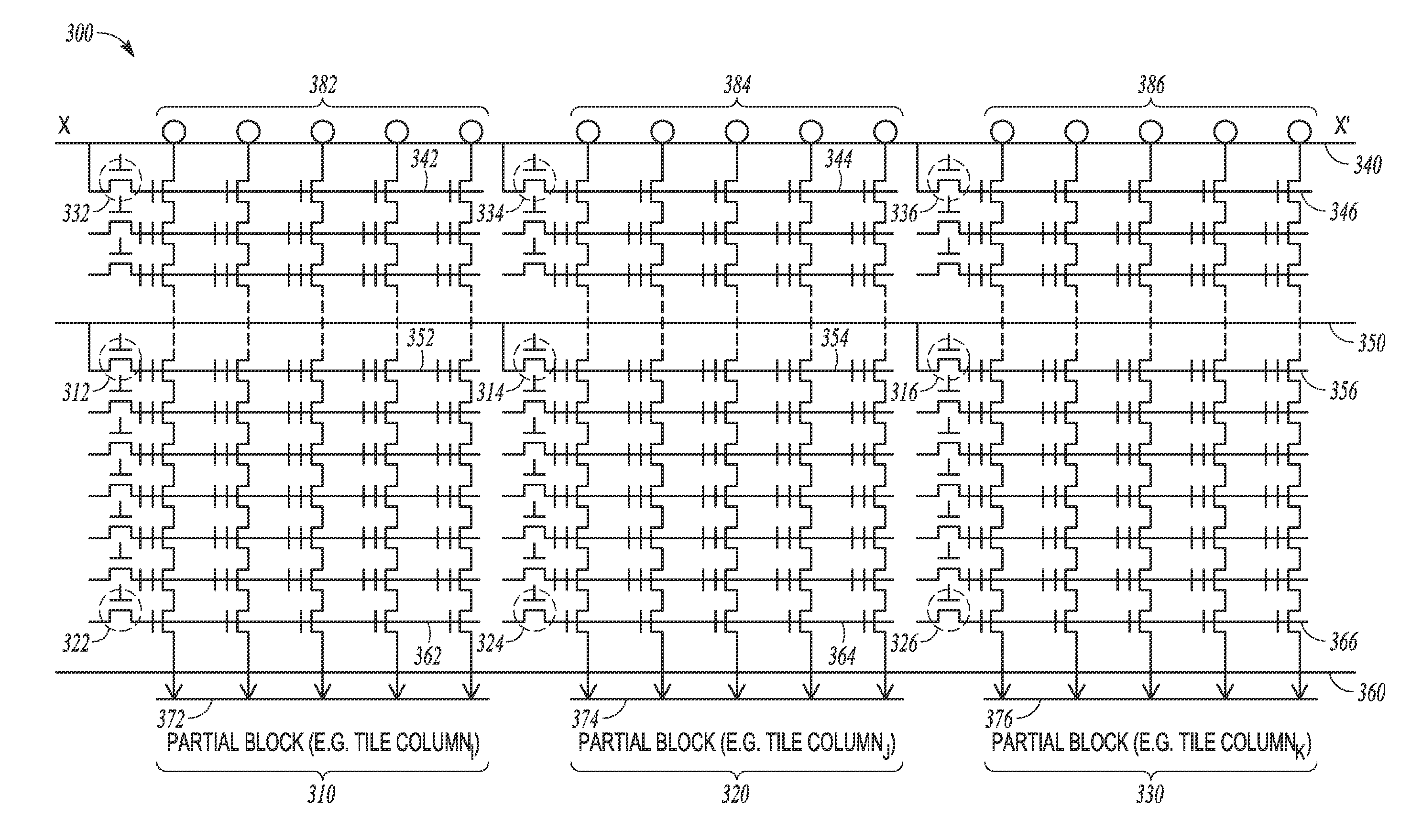
Methods and apparatuses are disclosed, such as those including a block of memory cells that includes strings of charge storage devices. Each of the strings may comprise a plurality of charge storage devices formed in a plurality of tiers. The apparatus may comprise a plurality of access lines shared by the strings. Each of the plurality of access lines may be coupled to the charge storage devices corresponding to a respective tier of the plurality of tiers. The apparatus may comprise a plurality of sub-sources associated with the strings. Each of the plurality of sub-sources may be coupled to a source select gate of each string of a respective subset of a plurality of subsets of the strings, and each sub-source may be independently selectable from other sub-sources to select the strings of its respective subset independently of other strings corresponding to other subsets.

Description

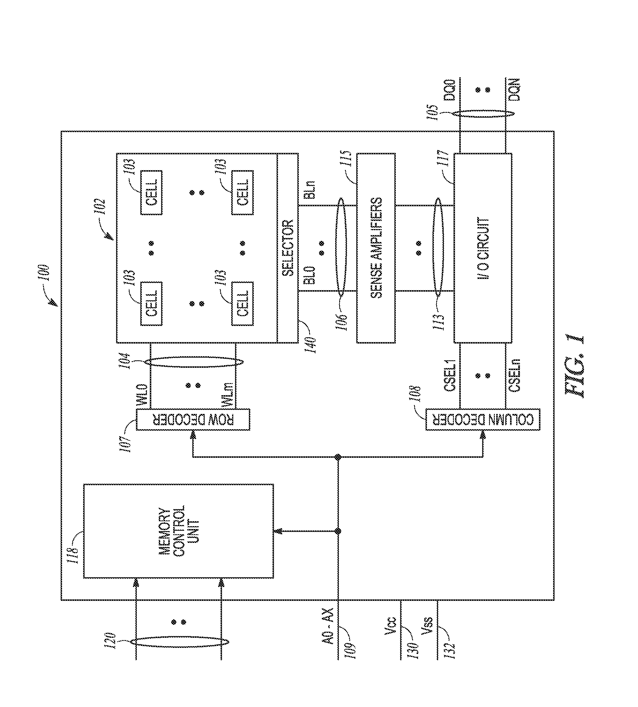
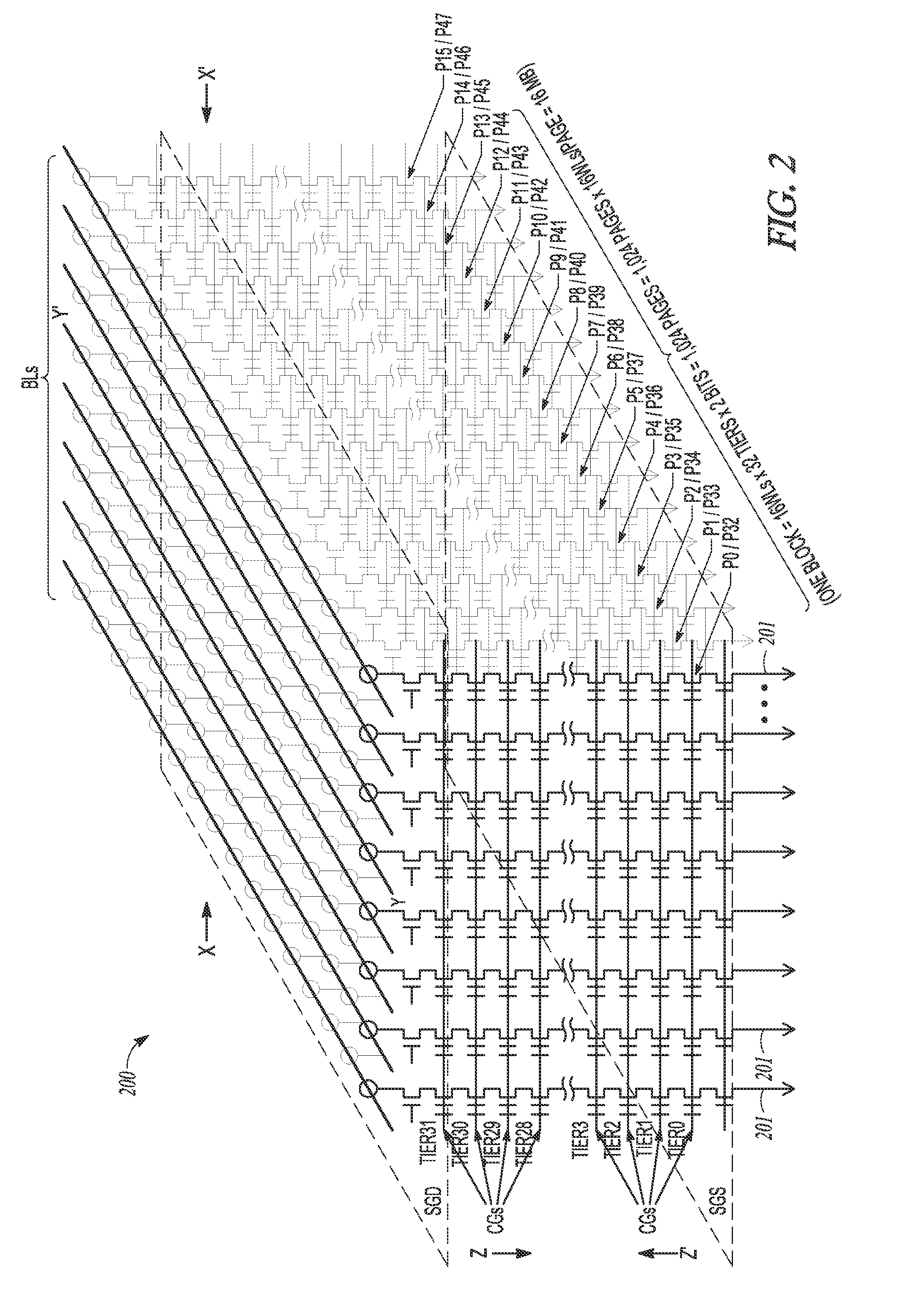
BACKGROUND[0001]A memory block of a memory device, such as a NAND memory, may comprise a group of strings of charge storage devices that share the same set of access lines. The memory block may be grouped into a plurality of pages, and each page may comprise all or a subset of the charge storage devices corresponding to a respective tier of each of the group of strings, for example, depending on whether the charge storage devices are single-level cells or multi-level cells.[0002]Under existing semiconductor memory techniques, a memory operation may be performed on an entire memory block (e.g., if the memory operation is an erase), or on a page within the memory block (e.g., if the memory operation is a program, read or verify). Accordingly, as the page size becomes larger, the power used during a data line swing or page buffer flip may increase, so that a relatively large amount of power may be consumed when relatively small amounts of data, such as 4 KB, are read, programmed, erase...

Claims


Application Information

Patent Timeline
IPC IPC(8): G11C16/04
CPCG11C16/0483G11C16/08G11C16/10G11C16/16G11C2213/75
Inventor FEELEY, PETER SEANSAKUI, KOJIGODA, AKIRA
Owner MICRON TECH INC
Learn More