Planetary gear reduction mechanism

Inactive Publication Date: 2014-01-30
NITTAN VALVE CO LTD
View PDF0 Cites 10 Cited by
  • Summary
  • Abstract
  • Description
  • Claims
  • Application Information

AI Technical Summary

Benefits of technology

The patent text describes a new planetary gear reduction mechanism. Unlike previous mechanisms, this one uses an external fixed sun gear and a driven external gear, which are meshed with external planetary gears. This allows for a larger reduction gear ratio by using smaller gears. The planetary gears can also be down-sized. The invention has greater freedom of choice in the module and gear teeth numbers of the sun gear, driven sun gear, and planetary gears. Additionally, the mechanism is simplistic in configuration and arrangement, reducing costs. The absence of internal gears also allows for the use of down-sized gears and low-cost manufacturing of versatile gear reducers with different gear ratios.

Problems solved by technology

First, the gear ratio of this planetary gear reduction mechanism is determined by the gear teeth numbers of the fixed ring gear, driven ring gear, and sun gear. Once the modules (or dimensions) and the gear teeth numbers of the ring gears are determined, the modules and gear teeth numbers of the planetary gears and the sun gear that mesh internally with the teeth of the ring gears are limited so that they can properly engage with the respective ring gears. In the planetary gears of the Patent Document 1, the higher is the gear ratio of the ring gear on the output shaft to the sun gear on the input shaft, the higher is the reduction gear ratio. However, if the gear teeth number of the sun gear is reduced relative to the ring gear having the same module as the sun gear, the installation space for the planetary gears becomes larger. Thus, in order to have the planetary gears to mesh with both of the ring gear and the sun gear, the planetary gears must have a large outer diameter, On the other hand, in order to prevent interference between neighboring planetary gears, it is necessary for the planetary gear reduction mechanism of the Patent Document 1 to limit, the number of planetary gears used.
Machining of such special gears, however, is difficult and increases manufacturing costs, thereby gives rise a difficult problem for down-sizing of the ring gears.

Method used


Image

  • Planetary gear reduction mechanism
  • Planetary gear reduction mechanism
  • Planetary gear reduction mechanism

Examples


first embodiment

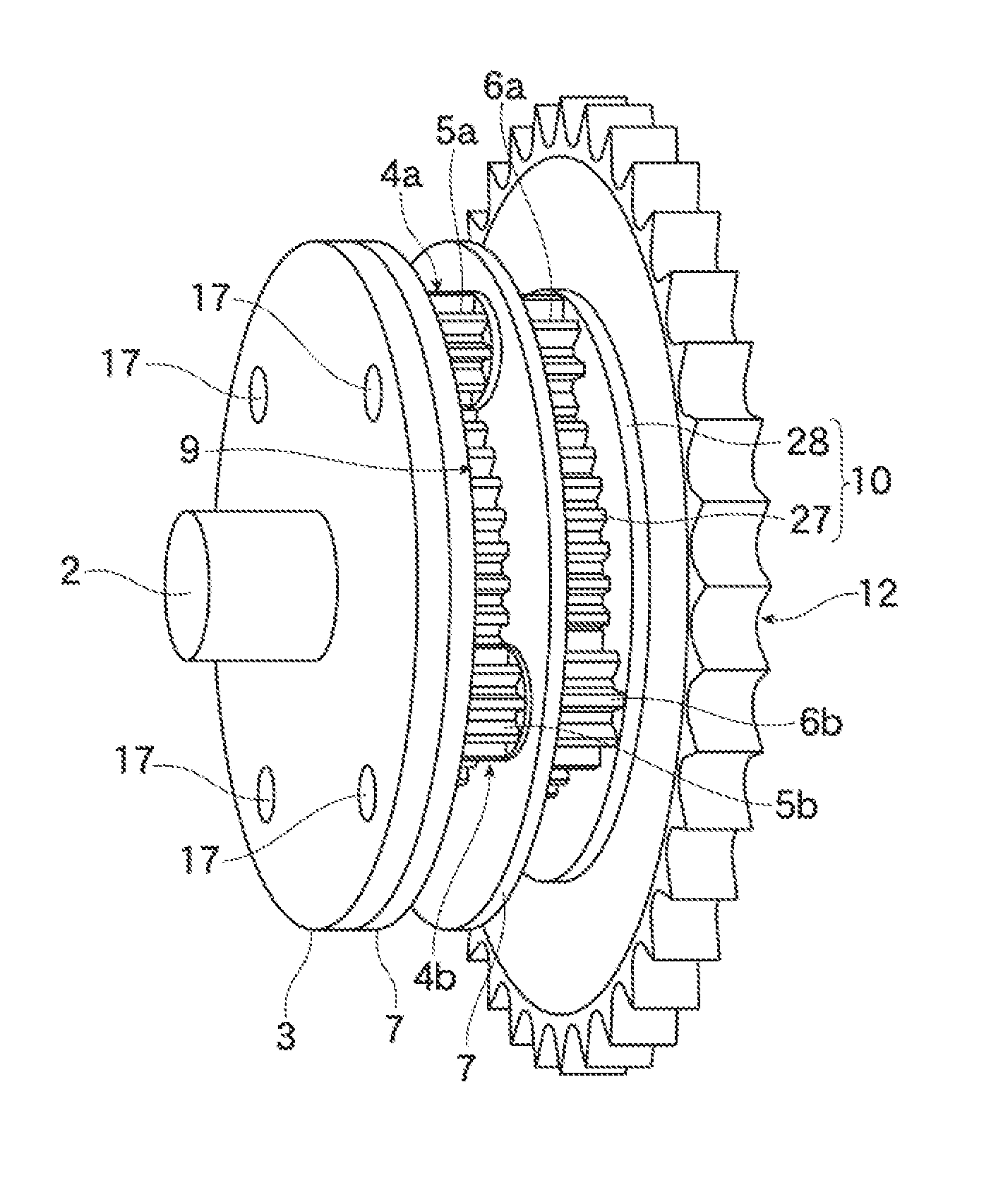
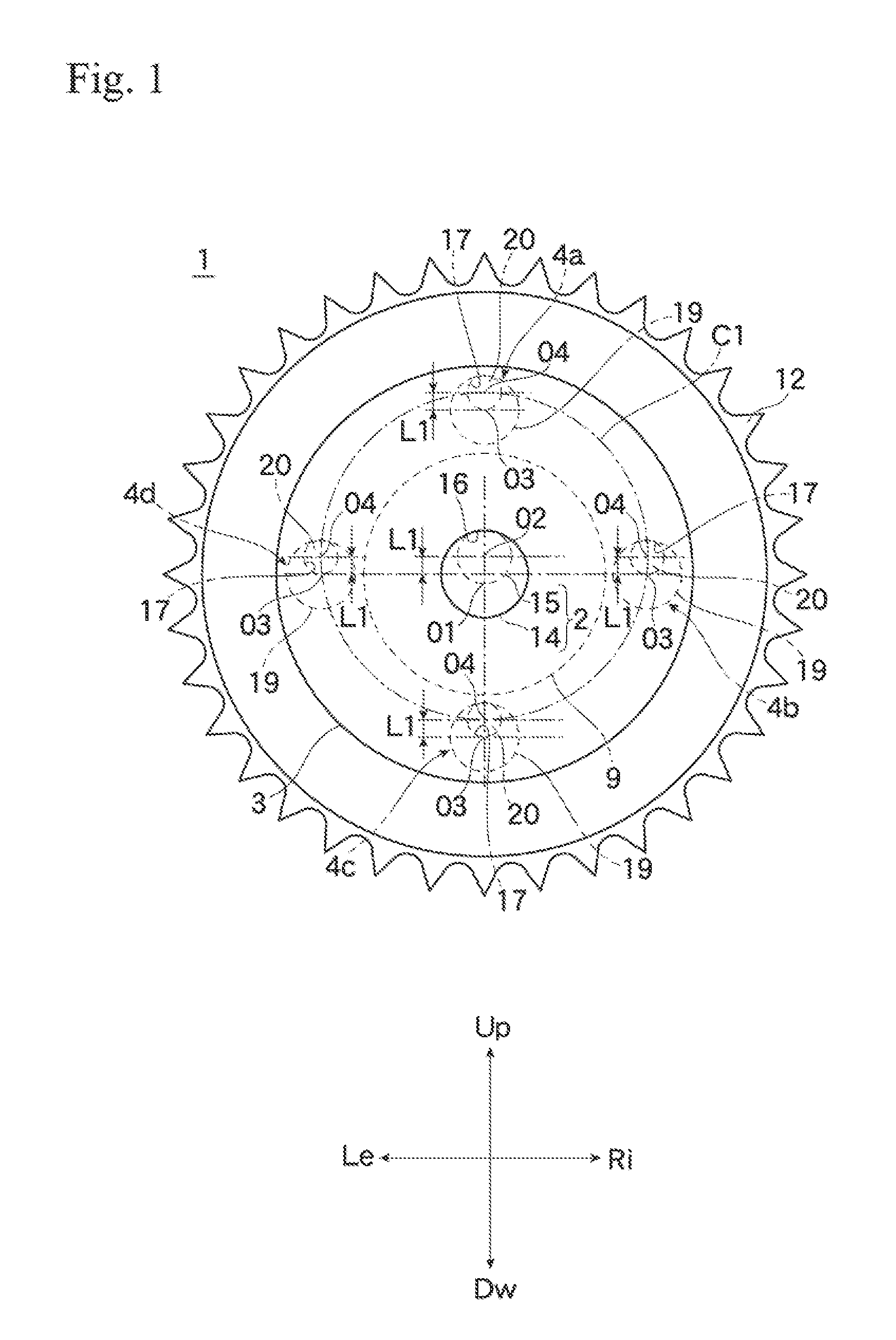
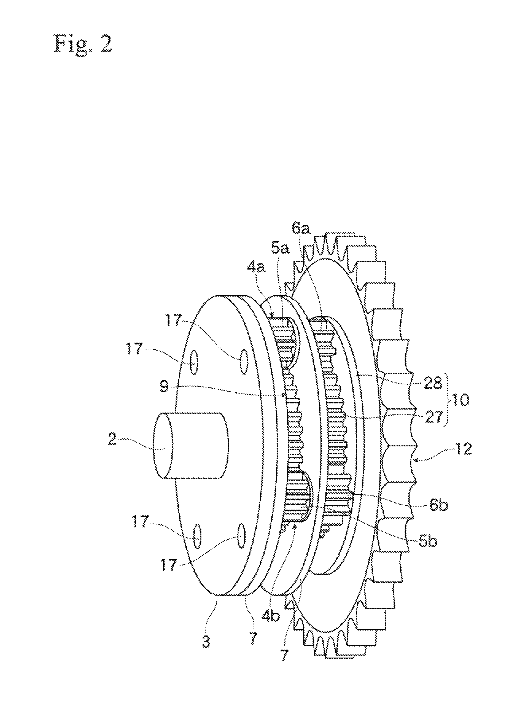
[0026]Referring to FIGS. 1 through 4, the invention will now be described in detail by way of example with reference to the In what follows the front, rear, upper, lower, left, and right sides of the planetary gear reduction mechanism will be denoted by symbols Fr, Re, Up, Dw, Le, and Ri, respectively.

[0027]A planetary gear reduction mechanism 1 has an input, shaft 2, an eccentric rotary plate 3, a set 4 of four planetary gears 4a-4d each consisting of a first gear (5a-5d) integrated with a second gear (6a-6d), a pair of supporting plates 7 for supporting the set 4 of planetary gears, a fixed sun gear 9, a driven sun gear 10, a center shaft 11, a sprocket 12 connected to the output shaft, and fixing bolts 13.

[0028]The eccentric shaft 15 shown in FIG. 1 is integral with the back side of the primary section 14, with the second rotational axis O2 of the eccentric shaft 15 offset upward from the first rotational axis O1 of the primary section 14 by a distance L1.

[0029]An eccentric rota...

second embodiment

[0061]Formed at the center of the cylindrical body 54a is a circular hole 54c which is open at the rear end of the flange section 54b and has the same inner diameter as the outer diameter of the front cylinder section 52a. A multiplicity of (six in the second embodiment) threaded female through-holes 54d are formed in the flange section 54b, in association with the respective through-holes 35 of the sprocket 12.

[0062]The second circular eccentric plate 53 is a disk shaped member formed with a large central hole 53a. Formed round the central hole 53a, and at the positions associated with the eccentric shaft 61 of the planetary gears 50a-50c, are circular holes 63 each having the same inner diameter as the outer diameter of the eccentric shaft 61. The centers of the circular holes 63 lie on a circular orbit centered at the central axis (not shown) offset downward from, and in parallel to, the first rotational axis O1 by the distance M. The inner diameter of the central hole 53a is lar...


PUM


Abstract

A compact planetary gear reduction mechanism having a universal gear reduction ratio is provided, which comprises: an input shaft rotatable about a first rotational axis; at least one planetary gear having a first and a second gear of the same shape integrated together rotatably about a third rotational axis (O3) but in out of phase with each other; an eccentric rotary plate for transmitting the rotational motion of the input shaft to a shaft mechanism which in turn transmits the eccentric rotation of the eccentric rotary plate to the planetary gear; an external fixed sun gear meshed with the first gear of the planetary gear; and an external driven sun gear to be connected to the output shaft of the gear reducer, having a different number of gear teeth than the fixed situ gear and meshed with the second gear of the planetary gear.

Description

TECHNICAL FIELD OF THE INVENTION[0001]This invention relates to a compact planetary gear reduction mechanism capable of having an arbitrary gear ratio, thus having a preferred larger reduction ratio than conventional ones, and more particularly, to a paradoxical planetary gear reduction mechanism having such feature.[0002]Patent Document 1 listed below discloses a planetary gear reduction mechanism obtained by improving a 3K-type paradoxical planetary gear reduction mechanism. Although a conventional 3K-type paradoxical planetary gear reduction mechanism has an advantage that it can provide a large gear ratio by reducing the difference in number of gear teeth (referred to as gear teeth difference) between a fixed ring gear and a driven ring gear as taught by Patent Document 1, its planetary gears cannot precisely mesh with these two ring gears having different gear teeth numbers unless the difference in the gear teeth numbers is an integral multiple of the number of planetary gears....

Claims


Application Information

Patent Timeline
IPC IPC(8): F16H1/28
CPCF16H1/28F16H1/32F16H2001/2881
Inventor KUBOTA, YUKIOKAMEDA, MICHIHIRO
Owner NITTAN VALVE CO LTD
Why Eureka
Try Eureka