Optical cable

Active Publication Date: 2007-05-10
SUMITOMO ELECTRIC IND LTD +1
View PDF1 Cites 28 Cited by
  • Summary
  • Abstract
  • Description
  • Claims
  • Application Information

AI Technical Summary

Benefits of technology

[0004] After studying a conventional optical cable, the inventors found out the following problems. Namely, in the tape-slotted type of optical cable, there easily occurs bending in the coated optical fibers during the manufacture and service, and the micro-bending loss tends to increase. On the other hand, the loose-tube type of optical cable is inferior to the tape-slotted type of optical cable in respect of the contained efficiency of the coated optical fibers. In this respect, it is considered that even in the loose-tube type of optical cable, the contained efficiency of the coated optical fibers can be improved such that an outer diameter of the cable is reduced while the number of the coated optical fibers to be contained is maintained. However, in that case, there occurs a problem that the transmission loss of the coated optical fiber may increase.
[0010] In accordance with an optical cable of the present invention, reduction of an outer diameter of the cable and / or improvement of contained efficiency of coated optical fibers can be achieved while an increase of transmission loss in the coated optical fibers is suppressed.

Problems solved by technology

A tape-slotted type of optical cable is excellent in contained efficiency of the coated optical fiber; there occurs easily bending in the coated optical fiber during the manufacture or using, which tends to increase micro-bending loss.
On the other hand, a loose-tube type of optical cable is characterized in that an increase of the micro-bending loss is small though it is inferior to the contained efficiency of the coated optical fibers as compared to the tape-slotted type of optical cable.

Method used


Image

  • Optical cable
  • Optical cable
  • Optical cable

Examples


Embodiment Construction

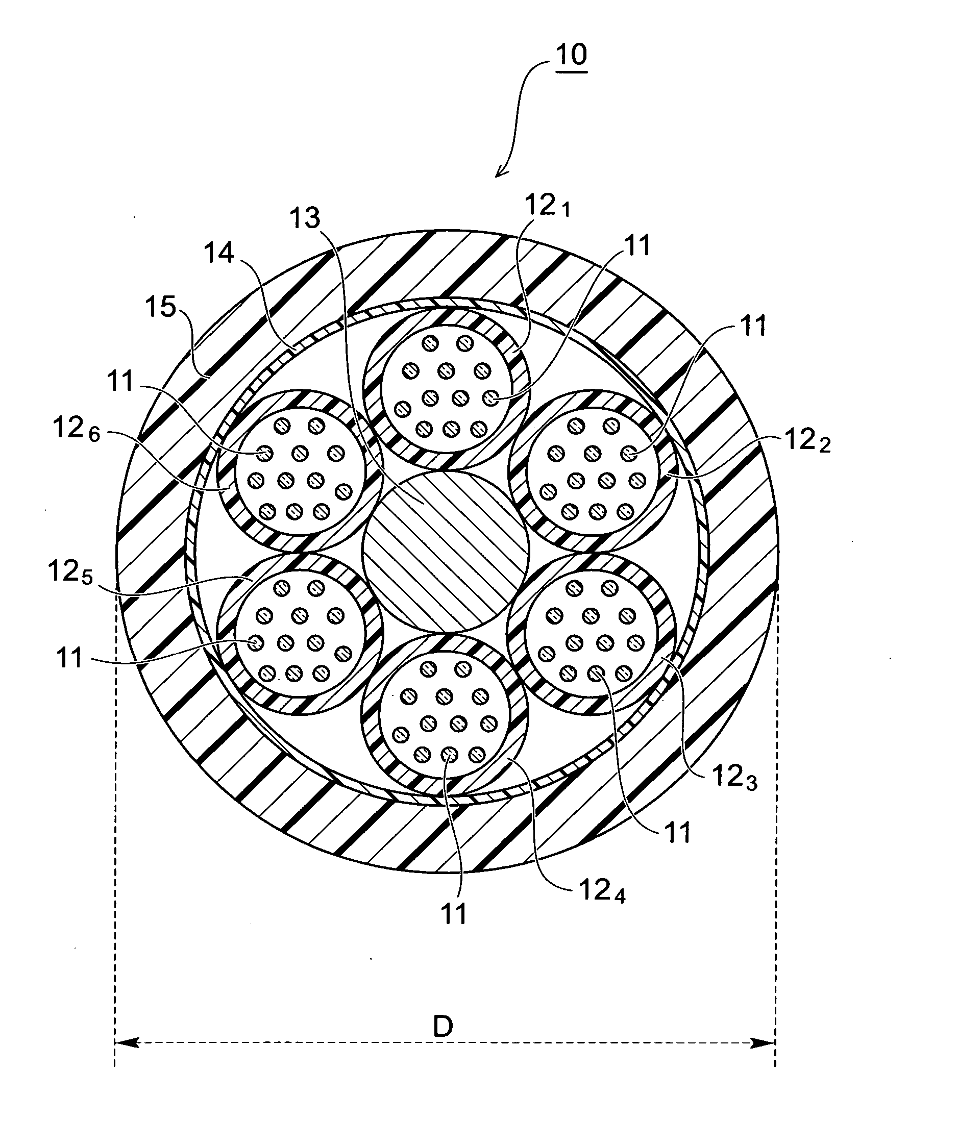
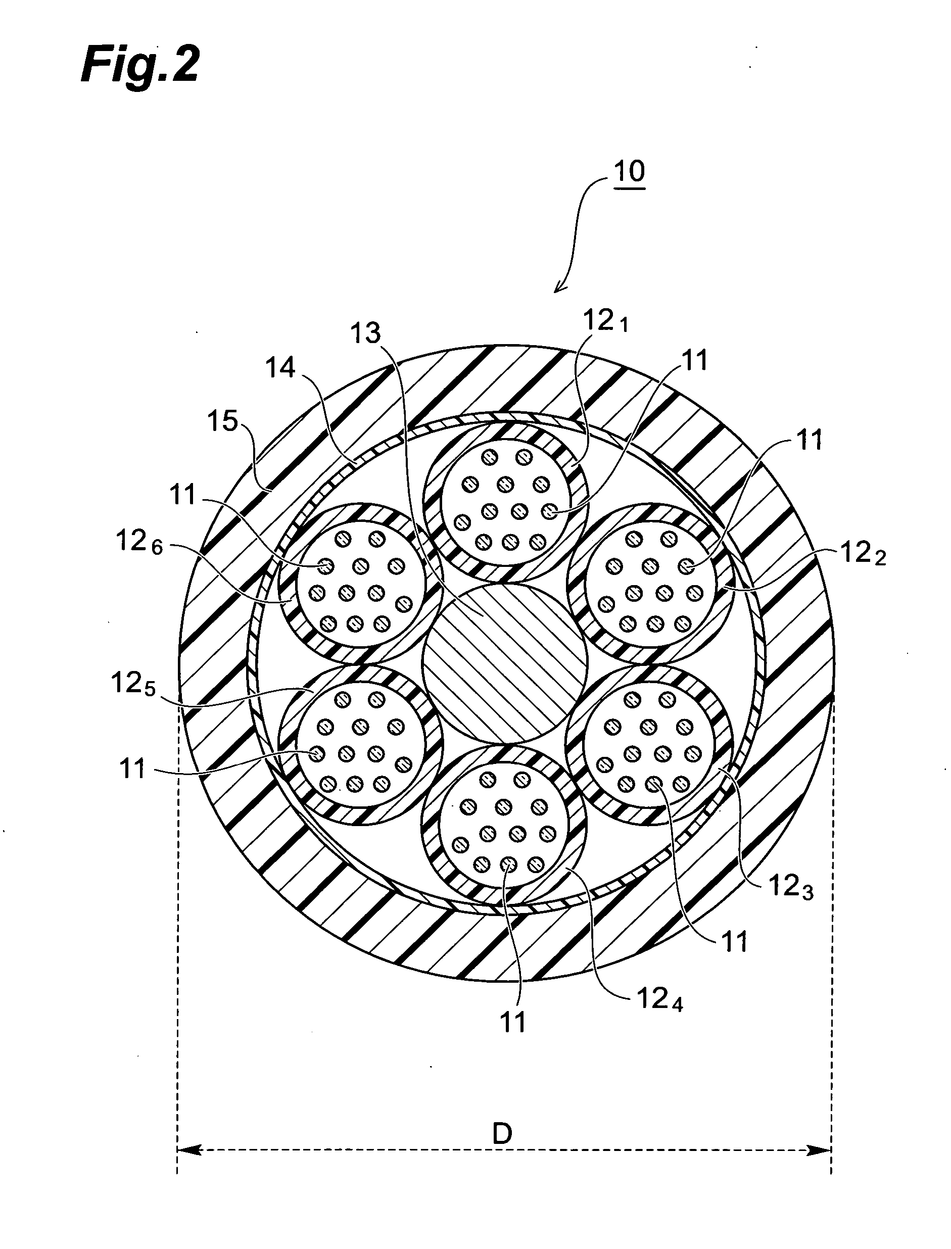
[0022] In the following, embodiments of the optical cable according to the present invention will be explained in detail with reference to FIGS. 1 to 10. In the explanation of the drawings, the same elements will be denoted by the same reference symbols and these redundant descriptions will be omitted.

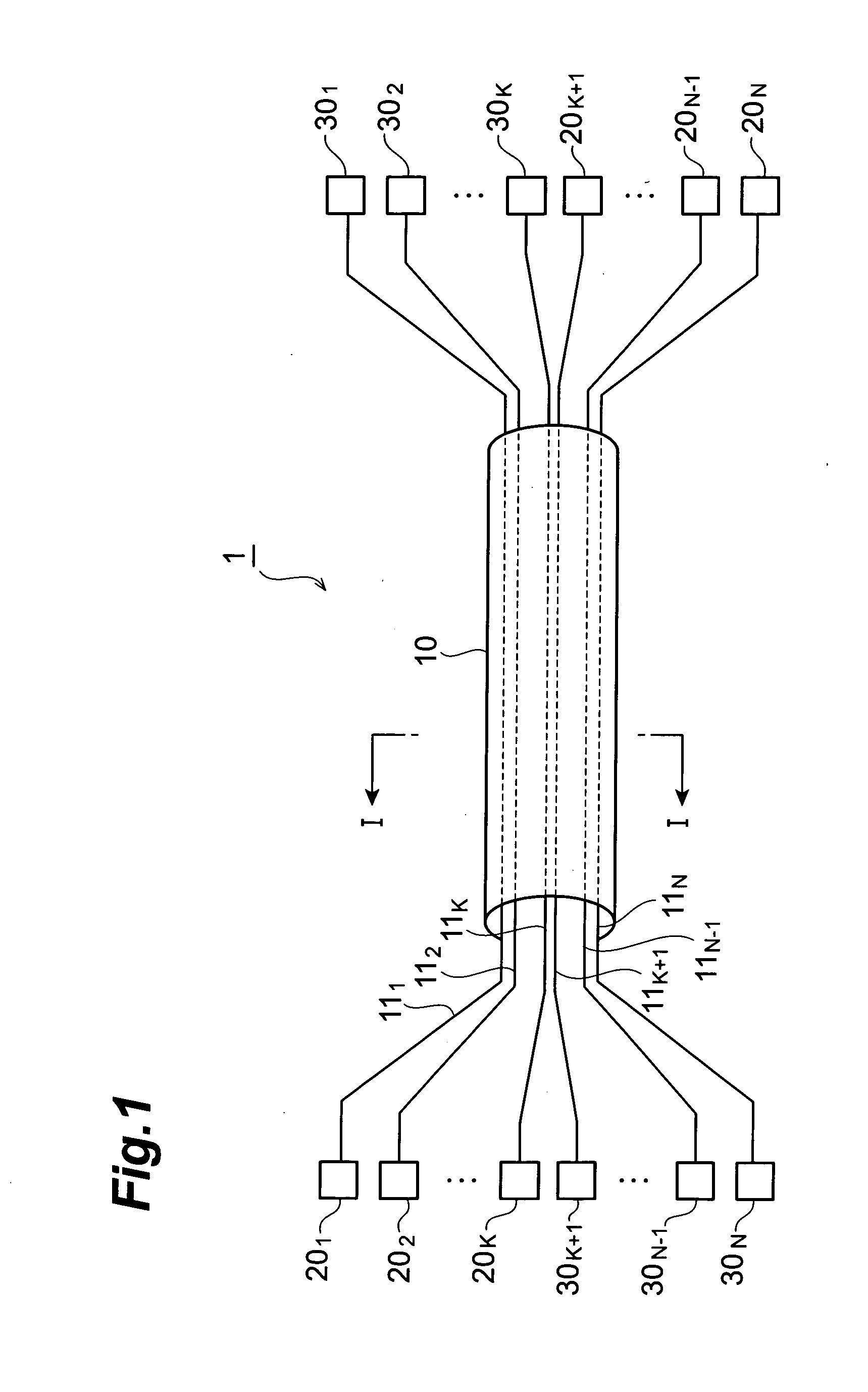
[0023]FIG. 1 is a diagram showing a schematic construction of an optical transmission system in which one embodiment of an optical cable according to the present invention is applied as an optical transmission line. An optical transmission system shown in FIG. 1 composes an optical cable 10, optical transmitters 201 to 20N, and optical receivers 301 to 30N. In the optical cable 10, N optical fibers 111 to 11N (N: an integer of two or more) are bundled. The optical transmitters 201 to 20K and the optical receivers 30K+1 to 30N are arranged on one end side of the optical cable 10, while the optical transmitters 20K+1 to 20N and the optical receivers 301 to 30K are arranged on the other ...


PUM


Abstract

An optical cable according to the present invention relates to an optical cable having a construction to enable reduction of a cable outer diameter, and / or improvement of contained efficiency of coated optical fibers while an increase of transmission loss in each coated optical fiber is suppressed. The optical cable has a loose-tube type of structure constructed by: a tension member; a plurality of tubes stranded together around the tension member; and an outer sheath covering the outer periphery of the plurality of tubes. One or more coated optical fibers are contained in each tube. A ratio of A / B is 6.3 or more but 7.0 or less, where each coated optical fiber has a mode field diameter A in a range of 8.6±0.4 μm at a wavelength of 1.31 μm, and where a fiber cutoff wavelength thereof is B μm.

Description

TECHNICAL FIELD [0001] The present invention relates to an optical cable constructed by bundling a plurality of optical fibers. BACKGROUND ART [0002] For the structure of an optical cable bundled by a plurality of coated optical fibers, a variety of structures such as tape-slotted type and loose-tube type are known (see Non-Patent Document 1). A tape-slotted type of optical cable is excellent in contained efficiency of the coated optical fiber; there occurs easily bending in the coated optical fiber during the manufacture or using, which tends to increase micro-bending loss. On the other hand, a loose-tube type of optical cable is characterized in that an increase of the micro-bending loss is small though it is inferior to the contained efficiency of the coated optical fibers as compared to the tape-slotted type of optical cable. [0003] Non-Patent Document 1: Gunther Mahike, et al., “Fiber Optic Cables, Fundamentals Cable Design System Planning”, 4th revised and enlarged edition, 20...

Claims


Application Information

Patent Timeline
IPC IPC(8): G02B6/44
CPCG02B6/441G02B6/4434
Inventor YOKOKAWA, TOMOYUKISASAOKA, EISUKE
Owner SUMITOMO ELECTRIC IND LTD
Why Eureka
Try Eureka