Device for the blind coupling of fluidic, electrical or similar supplies, to a receiving control mechanism

a technology of fluidic and electrical supplies, applied in the direction of coupling device connections, rotors, vessel construction, etc., can solve the problem of not being able to integrate the various connections easily

Active Publication Date: 2014-01-23
SN DETUDE & DE CONSTR DE MOTEURS DAVIATION S N E C M A
View PDF7 Cites 8 Cited by
  • Summary
  • Abstract
  • Description
  • Claims
  • Application Information

AI Technical Summary

Benefits of technology

[0027]Thus, using these connecting means, it is possible to be sure that the device of the invention is correctly positio

Problems solved by technology

Given the complex and relatively restricted and confined environment, it is not easy to integrate the various connections between the hidden internal supplies and the actuator hydraulic control mechanism distant therefrom.
Admittedly, connections could be

Method used


Image

  • Device for the blind coupling of fluidic, electrical or similar supplies, to a receiving control mechanism
  • Device for the blind coupling of fluidic, electrical or similar supplies, to a receiving control mechanism
  • Device for the blind coupling of fluidic, electrical or similar supplies, to a receiving control mechanism

Examples


Embodiment Construction

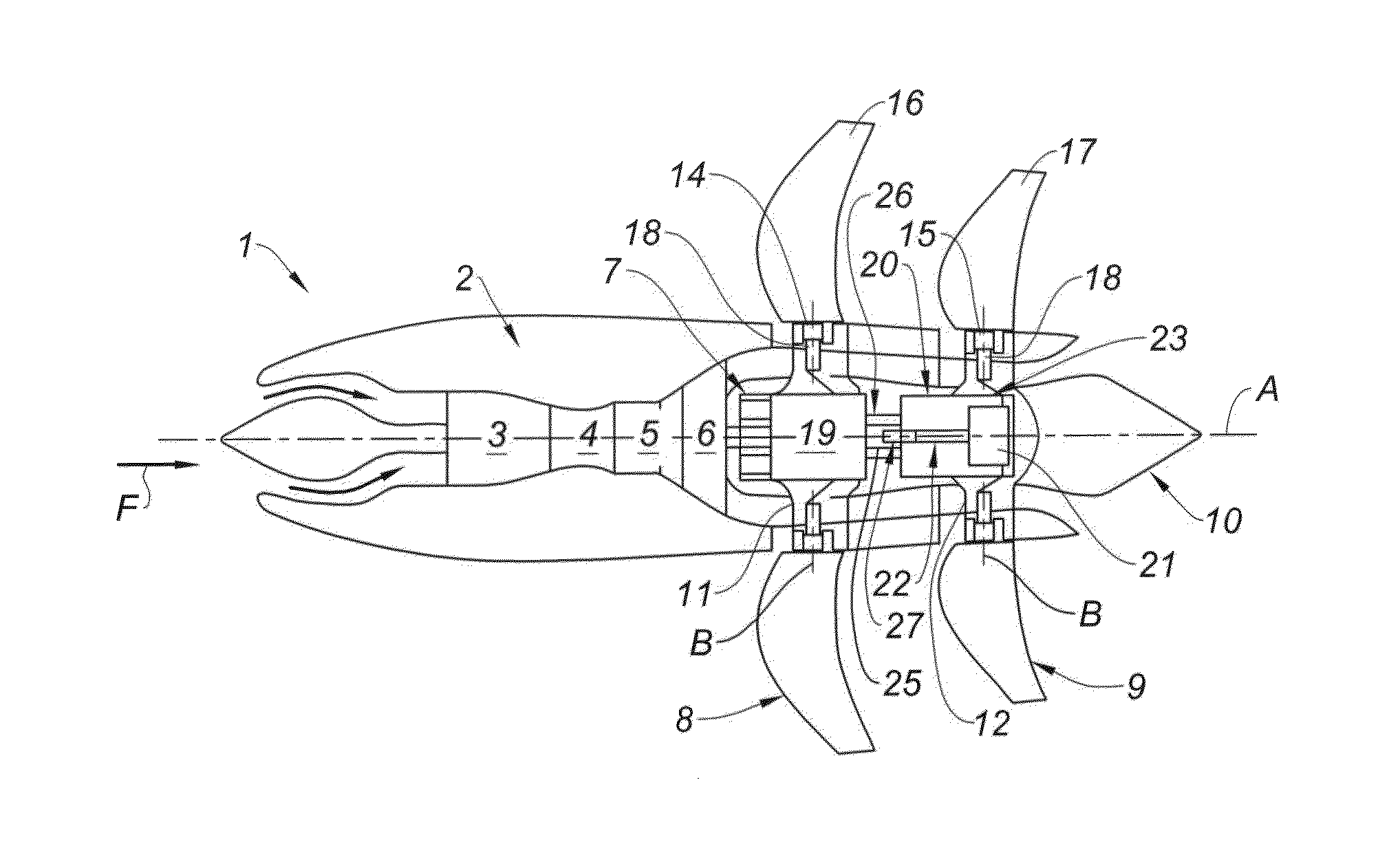
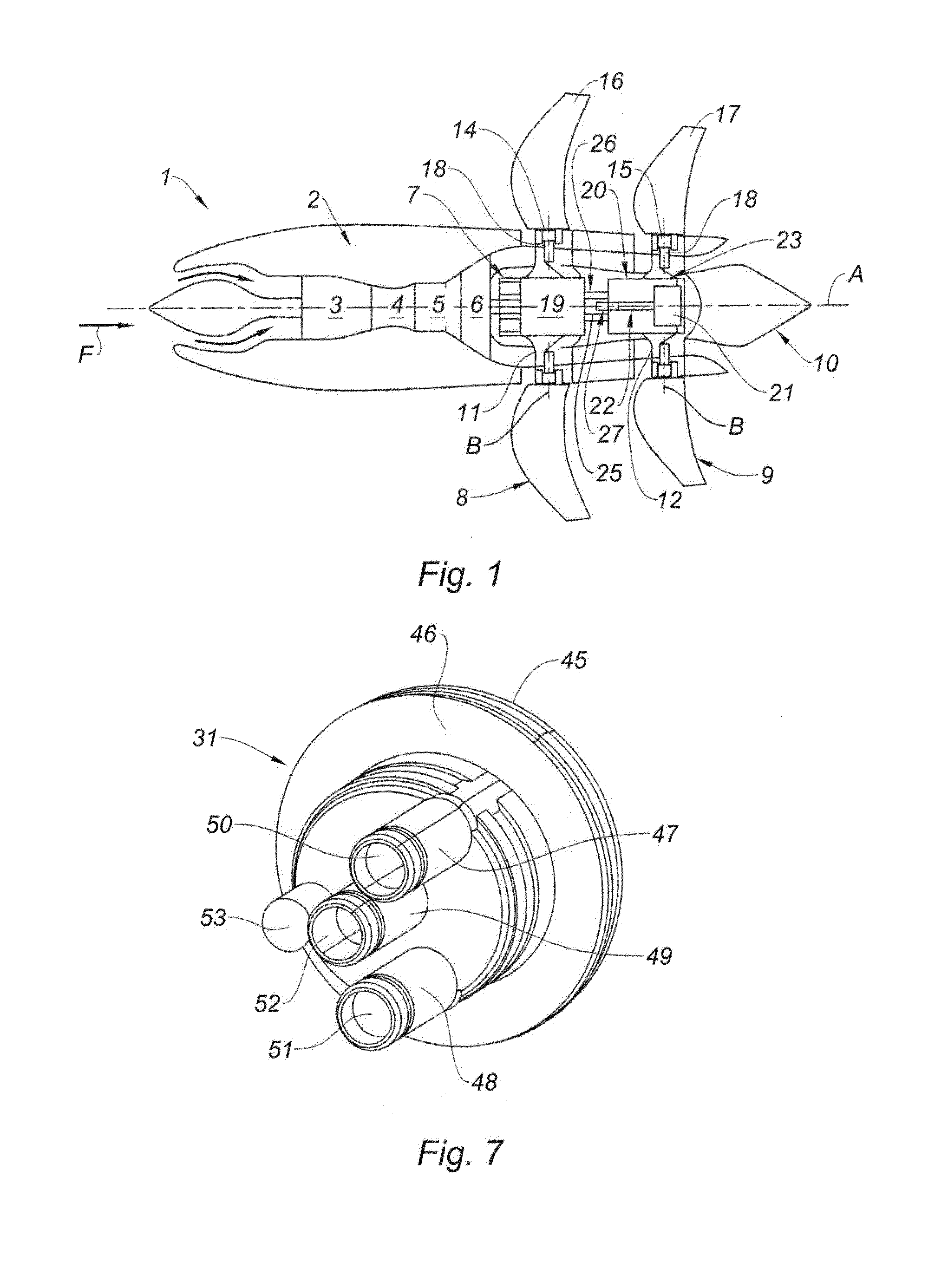
[0041]As FIG. 1 schematically shows, the unducted fan (“open rotor”) turbine engine 1, of longitudinal axis A, comprises in the usual way, from upstream to downstream in the direction of flow of the gaseous stream F inside a nacelle 2 of the turbine engine, one or two compressors 3 depending on the architecture of the gas generator, whether this be a single spool or a double spool design, an annular combustion chamber 4, a high-pressure turbine or two turbines, one high pressure and one intermediate pressure 5 depending on said architecture, and a low-pressure turbine 6 which, via reduction gear or an epicyclic gearbox 7 drives, in contra-rotatory fashion, two fans, one upstream 8 and one downstream 9 in the direction of the stream F, these fans being aligned coaxially along the longitudinal axis A of the turbine engine to form the fan unit. A jet pipe 10 terminates the turbine engine in the usual way.

[0042]The fans are arranged in parallel radial planes, perpendicular to the axis A...


PUM


Abstract

The device (27) can be housed coaxially inside a sleeve (25) in which the supplies are situated, and comprises:
    • a hollow cylindrical body (30) that fits inside the sleeve and accepts the mechanism (22) in the housing of the hollow body, with passages (33, 34, 36) for respectively connecting the supplies to said mechanism (22); and
    • a cover (31) which is integrated or fixed, removably, on the front side of the cylindrical body and connects the hidden supplies to the respective passages of the body.

Description

BACKGROUND OF THE INVENTION[0001]The present invention relates to a device for the blind coupling of supplies derived from generators or sources of fluidic, electrical or similar power, and which pass along inside a shaft or cylindrical sleeve which is static, to a receiving control mechanism such as, in the preferred application of the invention, a mechanism for controlling a system that controls the pitch of a turbomachine fan. The invention also relates to a fluidic assembly comprising a receiving control mechanism and a coupling device, and to a system for controlling the pitch of the blades of a turbomachine fan that comprises such a fluidic assembly.[0002]More specifically, although not exclusively, the device is intended to be mounted in turbine engines with pairs of contra-rotating propulsion fans, known by their English name of “open rotor” or “unducted fan” engines. However, without departing from the scope of the invention, it could also be mounted on a turboprop that has...

Claims


Application Information

Patent Timeline
IPC IPC(8): F16L21/00F01D7/02
CPCF16L21/00F01D7/02B64C11/385Y02T50/60B64C11/32B64C11/38F04D29/36B33Y80/00
Inventor CURLIER, AUGUSTINCHARIER, GILLES ALAINBELMONTE, OLIVIER
Owner SN DETUDE & DE CONSTR DE MOTEURS DAVIATION S N E C M A
Why Eureka
Try Eureka