
Separation method and separation device

Inactive Publication Date: 2014-01-09
KOBE STEEL LTD
View PDF3 Cites 3 Cited by
  • Summary
  • Abstract
  • Description
  • Claims
  • Application Information

AI Technical Summary

Benefits of technology

The present invention relates to a separation method and device for separating components from a mixture. The technical effects of the invention include the ability to increase the size of settlers to absorb the time required for separation, prevent contamination between fluids, and secure a steady separation state even with varying supply flow rates. Additionally, the invention allows for a reduction in the amount of solvent used and the reuse of solvent in subsequent stages of separation, resulting in cost savings and improved efficiency. The separation device can also be decreased in size while still allowing for a sure separation state.

Problems solved by technology

However, if the settlers are increased in size, the whole device for separation is also increased in size and the device is subjected to the restriction of the installation space.

Method used


Image

  • Separation method and separation device
  • Separation method and separation device
  • Separation method and separation device

Examples


first embodiment

[0026]First, as a first embodiment of a separation method of the present invention, an extraction method for extracting a specific component from the object fluid by dissolving the specific component in a solvent from the object fluid will be described.

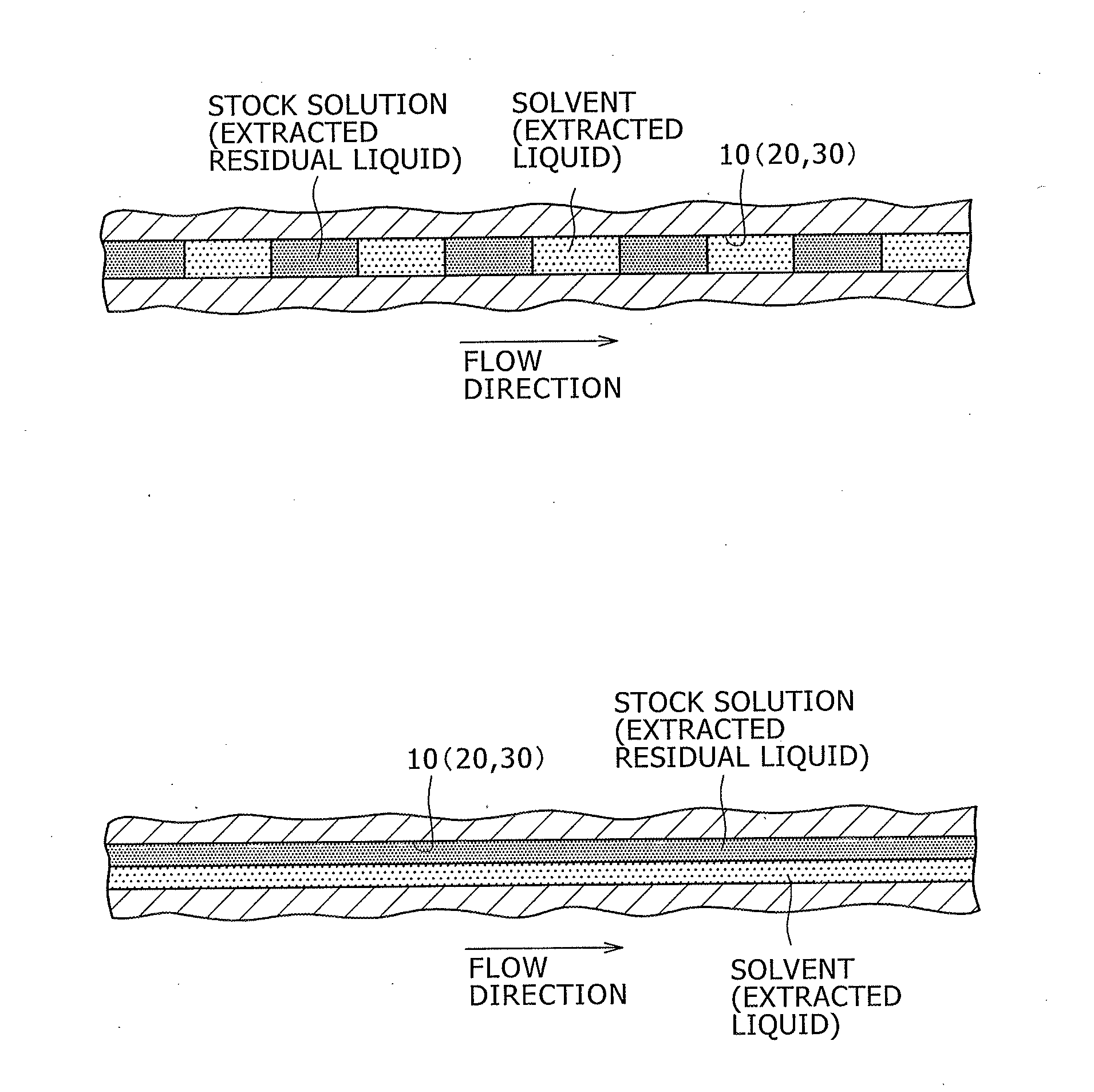
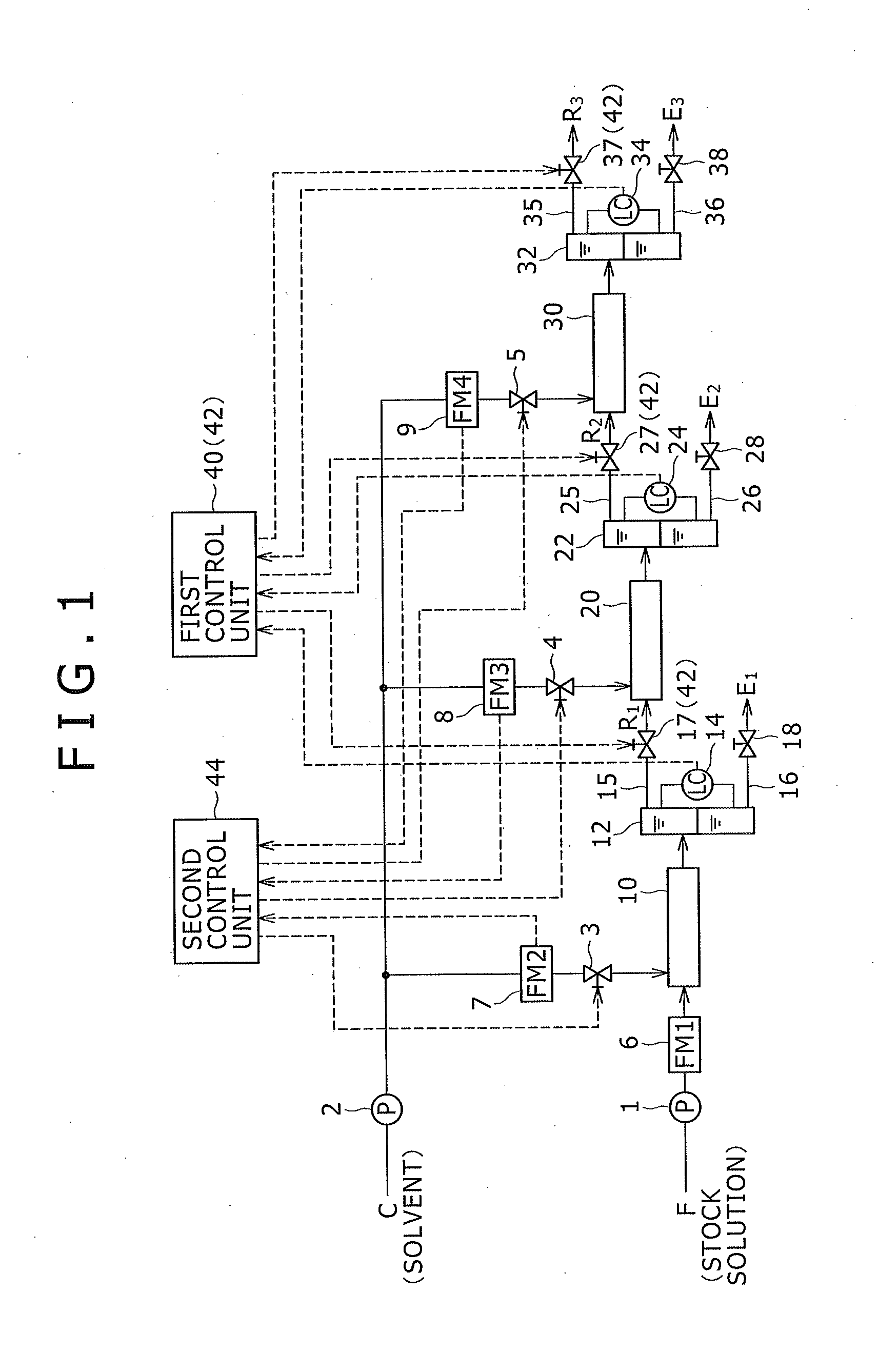
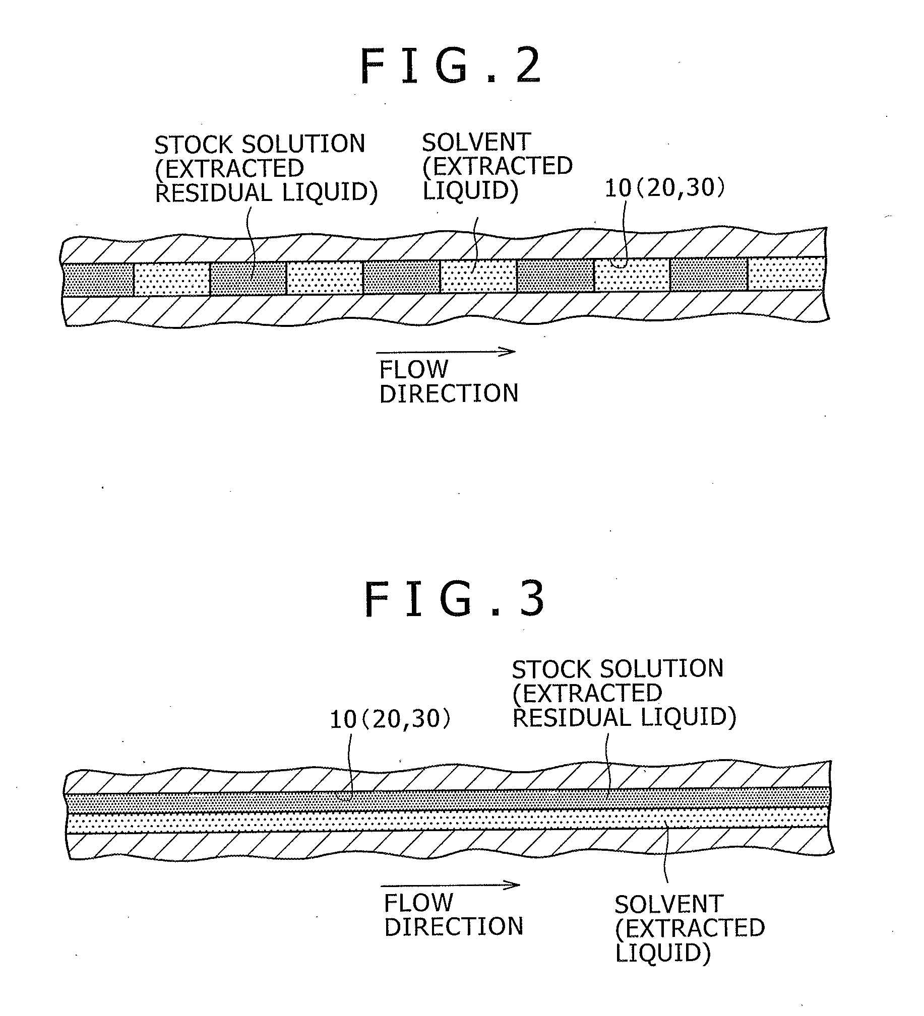
[0027]In the extraction method according to the first embodiment, extraction is performed with the use of an extraction device configured as shown in FIG. 1. The extraction device is included in the concept of “separation device” of the present invention. The extraction device comprises a first supply pump 1, a second supply pump 2, a first solvent flow rate regulating valve 3, a second solvent flow rate regulating valve 4, a third solvent flow rate regulating valve 5, a first flow meter 6, a second flow meter 7, a third flow meter 8, a fourth flow meter 9, a first microchannel 10, a first settler 12, a first liquid level gauge 14, a first upper side leading path 15, a first lower side leading path 16, a first upper side valve 17, a f...

second embodiment

[0058]Next, with reference to FIG. 4, the extraction method as a second embodiment of the separation method of the present invention will be described. In the extraction method according to the second embodiment, unlike the above-mentioned extraction method according to the first embodiment, the flow rate of the extracted residual liquid led out of the settlers 12, 22, 32 of the respective extraction stages to the upper side leading paths 15, 25, 35 is controlled according to the flow rate of the stock solution or the extracted residual liquid introduced into the corresponding microchannels 10, 20, 30 of the extraction stages.

[0059]Concretely, in an extraction device for use in the extraction method according to the second embodiment, as shown in FIG. 4, the first upper side leading path 15 is provided with a third flow meter 52, and the branch pipe connected to the second microchannel 20 among the piping connected to the second supply pump 2 is provided with a fourth flow meter 53....

third embodiment

[0068]Next, with reference to FIG. 5, the extraction method as a third embodiment of the separation method of the present invention will be described. In the extraction method according to the third embodiment, at the extraction step (dissolution step) of the preceding stage extraction operation, the extracted liquid led out to the lower side leading path 26 (36) at the leading step of the following stage extraction operation is fed to the preceding stage microchannel 10 (20) as a solvent.

[0069]Concretely, in an extraction device for use in the extraction method according to the third embodiment, as shown in FIG. 5, the second lower side leading path 26 is connected to the inlet side of the first microchannel 10, and the third lower side leading path 36 is connected to the inlet side of the second microchannel 20. Moreover, the second lower side leading path 26 is provided with a first returning pump 62 and a second flow meter 57, and the third lower side leading path 36 is provided...


PUM

PropertyMeasurementUnit
Flow rateaaaaaaaaaa
Heightaaaaaaaaaa
Specific gravityaaaaaaaaaa

Abstract

A separation method performs steps continuously and leads a solvent in which a separation object component is dissolved and a remaining fluid out of settlers under a separated state. The method includes leading a light fluid with a smaller specific gravity within the fluid in which the specific component is dissolved at the dissolution step and the remaining fluid out of settlers through upper side leading paths, and leading a heavy fluid with a larger specific gravity within the fluid in which the specific component is dissolved and the remaining fluid out of the settlers through lower side leading paths. A flow rate of the light fluid is controlled such that the height position of an interface between the light fluid and the heavy fluid within the settlers is maintained between the height position of connection parts of the upper side leading paths and the height position of connection parts of the lower side leading paths to the settlers.

Description

BACKGROUND OF THE INVENTION[0001]1. Field of the Invention[0002]The present invention relates to a separation method and a separation device for separating a specific component from the object fluid by dissolving the specific component in a solvent from the object fluid containing the specific component.[0003]2. Description of the Related Art[0004]Conventionally, a variety of separation methods for separating a specific component from the object fluid are known, and an example of the separation methods is shown in a non-patent literature Soko ga Shiritai Kagaku no Hanashi (That's the Chemical Topic We Want to Know) “Bunri Gijutsu (Separation Technology)”', The Nikkan Kogyo Shimbun, Ltd., the publication of the first impression of the first edition on Jun. 28, 2008, p. 103.[0005]Concretely, in the above non-patent literature, as an example of the separation methods, an extraction method for extracting a target component by a solvent from a stock solution which is an object fluid is d...

Claims


Application Information

Patent Timeline
IPC IPC(8): B01D11/04
CPCB01D11/0484B01D11/0496B01D11/0488
Inventor MATSUOKA, AKIRANOISHIKI, KOJI
Owner KOBE STEEL LTD
Learn More