
Connector

Active Publication Date: 2014-01-02
MOLEX INC
View PDF5 Cites 7 Cited by
  • Summary
  • Abstract
  • Description
  • Claims
  • Application Information

AI Technical Summary

Benefits of technology

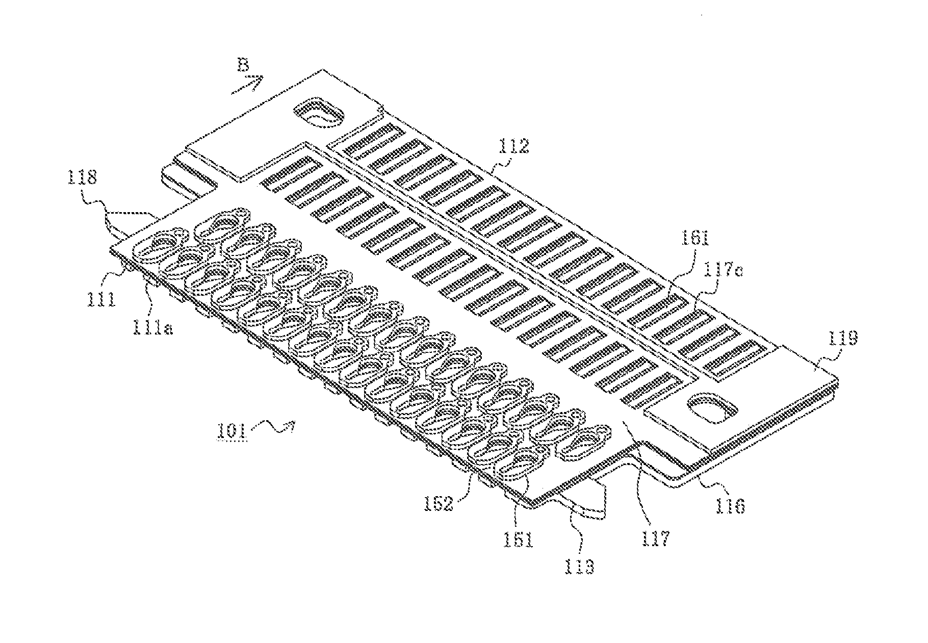
The present disclosure aims to solve the problems with conventional connectors by providing a reliable and compact connector that can absorb positioning errors and prevent excessive shaving or deformation of the terminals. This is achieved by giving the shapes of the openings of the terminals engaged with the other half of the connector left-right asymmetry. The technical effect is an increase in reliability while maintaining compactness and low-profile of the connector.

Problems solved by technology

However, in the conventional connector, due to the effects of tolerances in manufacture and the like, positioning errors in the male-side electrode protrusions and positioning errors in the terminal-enclosing openings 954 of the male-side electrode patterns 951 may occur.
If such positioning errors occur, there is a risk of excessive shaving or deformation of the male-side electrode protrusions or terminal-enclosing openings 954 occurring.
In particular, as the electrodes are miniaturized or given higher densities accompanying progress in the miniaturization or increase in density of connectors, the problems arising due to positioning errors related to the dimensions and positions of electrodes become greater.

Method used


Image

  • Connector
  • Connector
  • Connector

Examples


Embodiment Construction

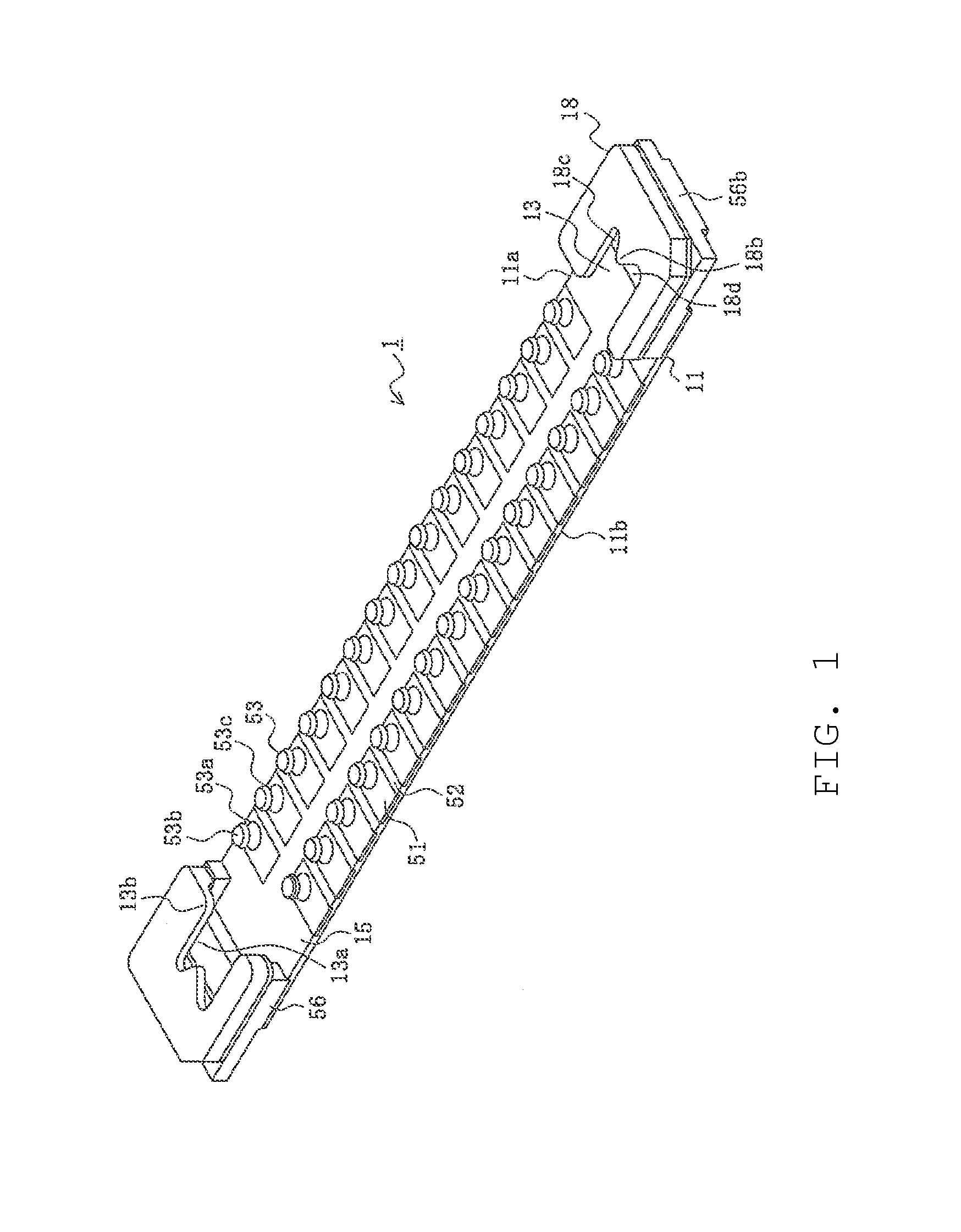
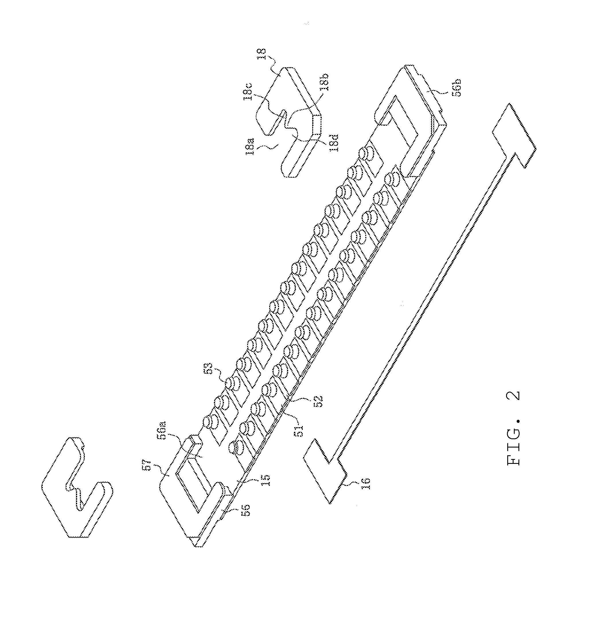
[0029]While the Present Disclosure may be susceptible to embodiment in different forms, there is shown in the Figures, and will be described herein in detail, specific embodiments, with the understanding that the Present Disclosure is to be considered an exemplification of the principles of the Present Disclosure, and is not intended to limit the Present Disclosure to that as illustrated.

[0030]As such, references to a feature or aspect are intended to describe a feature or aspect of an example of the Present Disclosure, not to imply that every embodiment thereof must have the described feature or aspect. Furthermore, it should be noted that the description illustrates a number of features. While certain features have been combined together to illustrate potential system designs, those features may also be used in other combinations not expressly disclosed. Thus, the depicted combinations are not intended to be limiting, unless otherwise noted.

[0031]In the embodiments illustrated in ...


PUM


Abstract

A connector characterized in that it: is a connector that has a plurality of plate-shaped terminals that include openings able to enclose protruding terminals of the other half of the connector, and that mates with the other half of the connector. The openings comprise a wide portion, a narrow portion and a transitional portion that transitions from the wide portion to the narrow portion, and, in a top view, are provided with a first shape that is left-right asymmetric with respect to the centerline of the plate-shaped terminals, or a second shape whereby the first shape is inverted about the centerline. The plate-shaped terminals are arrayed lined up in the width direction of the connector, and arrayed such that the plate-shaped terminals comprising an opening having the first shape and the plate-shaped terminals comprising an opening having the second shape alternate.

Description

REFERENCE TO RELATED APPLICATIONS[0001]The Present Disclosure claims priority to prior-filed Japanese Patent Application No. 2012-144419, entitled “Connector,” filed on 27 Jun. 2012 with the Japanese Patent Office. The content of the aforementioned patent application is incorporated in its entirety herein.BACKGROUND OF THE PRESENT DISCLOSURE[0002]The Present Disclosure relates, generally, to a connector.[0003]Conventionally, in personal electronic equipment, in order to handle the greater miniaturization and increased performance of the devices and components, demands have been made of connectors too for greater miniaturization and higher density. In order to meet these demands, there have been proposals to form a plurality of conductor patterns upon insulating substrates and provide connectors that connect the ends of these conductor patterns to other substrates and the like. An example is disclosed in Japanese Patent No. 2007-114710, the content of which is hereby incorporated by ...

Claims


Application Information

Patent Timeline
IPC IPC(8): H01R24/00
CPCH01R24/005H01R12/89
Inventor SAGAYAMA, AKIRANIITSU, TOSHIHIRO
Owner MOLEX INC
Learn More