Resolver and multiple-rotation detector

a technology of multiple rotation and detector, applied in the field of multiple rotation detector, can solve the problems of easy influence of the solver and the solver, difficult correction, and error at the calculated absolute angular position, and achieve the effects of reducing the influence of magnetic field noise, high noise immunity, and high degree of accuracy

Inactive Publication Date: 2014-01-02
OKUMA CORP
View PDF4 Cites 4 Cited by
  • Summary
  • Abstract
  • Description
  • Claims
  • Application Information

AI Technical Summary

Benefits of technology

The present invention provides a resolver and a multiple-rotation detector that have high noise immunity and a high degree of accuracy. The detection section employs a structure that reduces the influence of magnetic field noise from outside, allowing for accurate detection even in high magnetic field noise environments without the need for expensive noise reduction measures.

Problems solved by technology

Consequently, the resolver and the multiple-rotation detector are easily subjected to the influence of magnetic field noise from outside.
As a result, an error occurs at the calculated absolute angular position.
Moreover, in a case where a plurality of resolvers are disposed on the same plane, an amount of magnetic interference is changed and complicated depending on entering directions of the noise magnetic flux, making the correction difficult.

Method used


Image

  • Resolver and multiple-rotation detector
  • Resolver and multiple-rotation detector
  • Resolver and multiple-rotation detector

Examples


Embodiment Construction

[0028]A reluctance resolver which is a preferred embodiment of a multiple-rotation detector according to the present invention will be described below in accordance with the drawings.

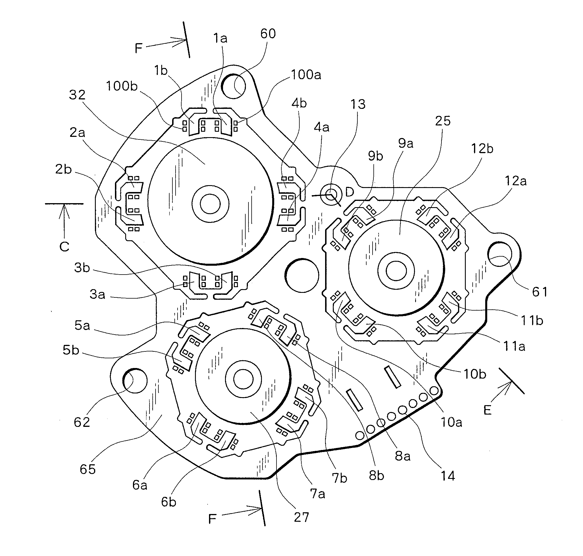
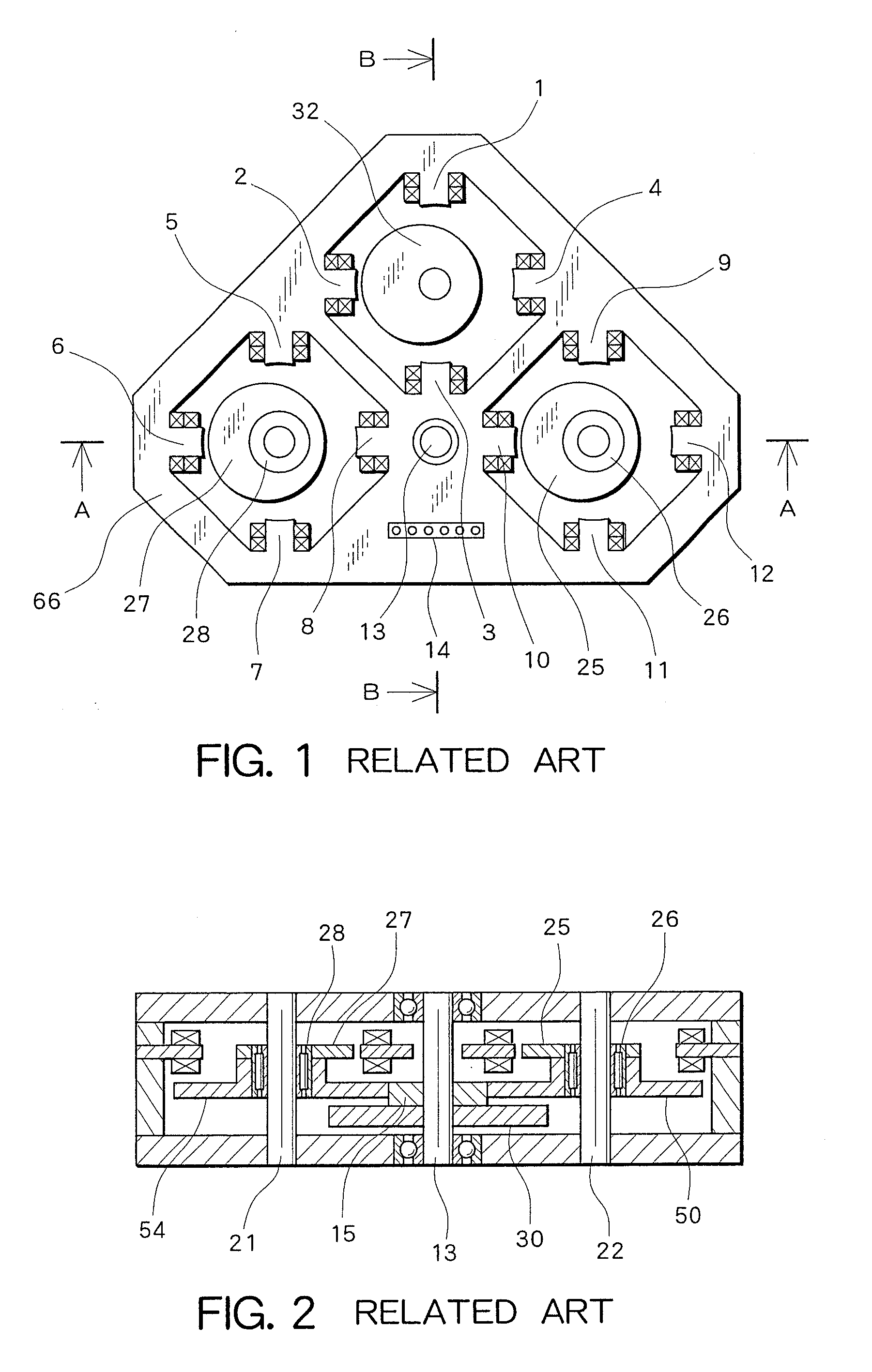
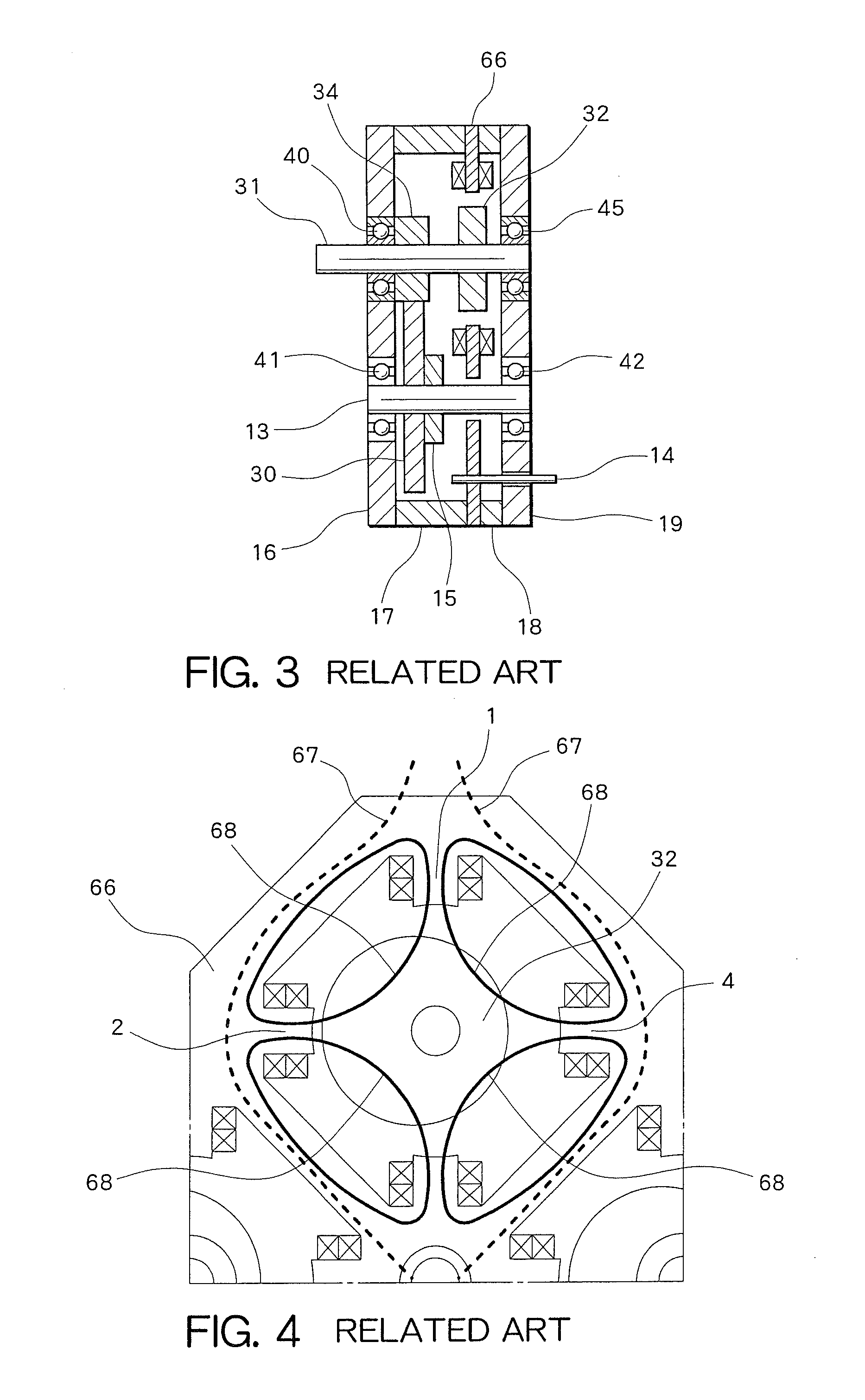
[0029]FIG. 5 is a diagram of a reluctance resolver in a preferred embodiment of the present invention which is seen from a surface perpendicular to an axis thereof. FIG. 6 is a cross-sectional view taken along the portion C-D-E illustrated in FIG. 5. FIG. 7 is a cross-sectional view taken along the portion F-F illustrated in FIG. 5. FIG. 8 is an enlarged view of the periphery of a rotor 32 illustrated in FIG. 5. Structures similar to those of the prior art illustrated in FIGS. 1, 2, 3, and 4 are described using the same reference numerals, and descriptions thereof are omitted.

[0030]In the reluctance resolver in FIG. 5, three resolvers are disposed on the same plane. Further, eight teeth 1a to 4b are provided on the periphery of a rotor 32, eight teeth 5a to 8b are provided on the periphery of a rotor 27...


PUM


Abstract

A stator includes: a core formed by laminating magnetic steel sheets; and an excitation coil and a detection coil which are wound around teeth provided at the core. The core includes a peripheral section which is disposed to surround the rotor and a detection section which is disposed at the interior of the peripheral section and has the teeth. When the magnetic steel sheets are laminated, each of the magnetic steel sheets forming the core includes a portion which constitutes the peripheral section and a portion which constitutes the detection section. The detection section is substantially U-shaped, and both sides of the U-shape become a pair of teeth which form one phase. A base portion of the substantially U-shape of the detection section connects. with the peripheral section, and gaps are provided between the peripheral section and a part of the base portion which is the root of the teeth.

Description

PRIORITY INFORMATION[0001]This application claims priority to Japanese Patent Application No. 2012-146635 filed on Jun. 29, 2012, which is incorporated herein by reference in its entirety.BACKGROUND[0002]1. Technical Field[0003]The present invention relates to a resolver and a multiple-rotation detector which comprises a plurality of resolvers.[0004]2. Related Art[0005]A resolver includes a rotor which rotates together with a shaft and a stator which is located around the rotor. The rotor is shaped like an eccentric disc, an ellipse, or the like in which a distance between the rotation center of the rotor and the surface thereof is different depending on an angular position thereof. Accordingly, when the rotor rotates, a gap between the rotor and the stator is changed at a certain fixed position on the stator. The stator includes a detector which detects this gap. The detector includes a coil, detects the change of a magnetic flux density caused by the change of a gap between the ro...

Claims


Application Information

Patent Timeline
Patent Type & Authority Applications(United States)
IPC IPC(8): G01B7/30H02K24/00
CPCG01B7/30G01D5/2046G01D2205/26G01D2205/73
Inventor KAWAMURA, SOICHIYURA, MOTOZUMISHIBATA, SHINJI
Owner OKUMA CORP
Why Eureka
Try Eureka