Micro-gripper

a micro-gripper and micro-gripper technology, applied in the field of micro-grippers, can solve the problems of unfavorable micro-gripper operation, failure of the gripper, and object detachment in an undesired way from the micro-gripper, and achieve the effects of reducing manufacturing costs, high manufacturing precision, and convenient chang

Inactive Publication Date: 2014-01-02
CARL ZEISS MICROSCOPY GMBH
View PDF2 Cites 0 Cited by
  • Summary
  • Abstract
  • Description
  • Claims
  • Application Information

AI Technical Summary

Benefits of technology

The present invention aims to provide a method for producing a cost-effective micro-gripper with parallel clamping faces that can accommodate, transport, and hold material samples in a TEM or SEM. The lateral dimensioning and shaping of the micro-gripper is achieved through a structuring of layers during material deposition, which allows for a customized shape adapted to meet different requirements. Additionally, simultaneous production of multiple micro-grippers on one substrate is possible, reducing manufacturing costs while also allowing for easy customization of shape.

Problems solved by technology

The grippers cited up to this point all have the disadvantage that it is necessary to feed electrical or magnetic energy to the actuator to grip and hold objects.
If this is interrupted or disturbed, a failure of the gripper occurs, that is, the object may detach from the micro-gripper in an undesired way.
In addition, the necessary electrical adaptation of the micro-gripper in the required dimensions in the micrometer range is complex and costly.
The micro-grippers described above are not or are not optimally suitable for this purpose for the cited reasons, however.
The micro-gripper disclosed in US 2002 / 0166976A1 has the disadvantage that it is not technically possible by the specified production method to produce the faces adjoining the receptacle slot, that is, the internal clamping faces on the gripping elements, exactly parallel to one another.
This finally results in an uneven distribution of clamping forces on the object to be held and has the danger that objects clamped between the clamping faces may shift in relation to the micro-gripper.
Furthermore, the described method is only suitable in a limited way, and / or not at all for mass production, because exact fixing and positioning of the tungsten wire is required individually for each micro-gripper, before the processing using the ion beam may be performed, which makes the production method time-consuming and costly.

Method used


Image

  • Micro-gripper
  • Micro-gripper
  • Micro-gripper

Examples


Embodiment Construction

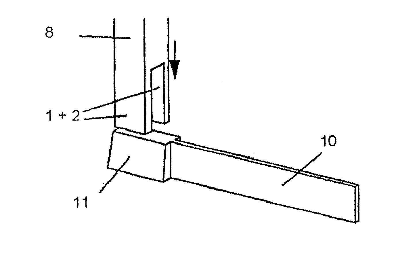
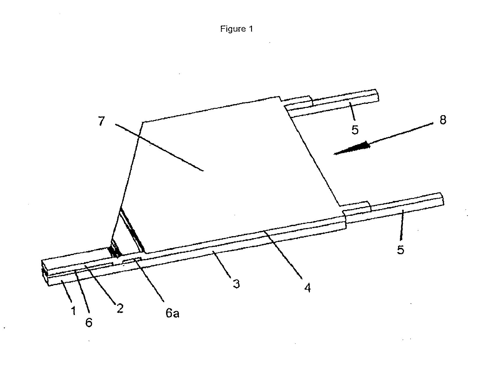
[0042]FIG. 1 shows a perspective view of a micro-gripper 8 produced according to the invention, which is implemented as a planar body. The planar body 8 comprises a first material layer 3 and a second material layer 4, which is bonded to the first material layer 3. The planar body 8 may be divided into a base body area having the associated planar body surface part 7 and a gripping body area having the gripping elements 1 and 2, between which the receptacle slot 6 is located. Furthermore, a continuous gap 6a running transversely to the gripping elements 1, 2 is provided in the connection area between base body and gripping body in the micro-gripper 8 shown. This gap is used for improved introduction of forces which arise by an elastic deformation of the gripping elements 1, 2 into the material layers 3 and 4. Thin webs 5 are provided on the right side of the micro-gripper 8 shown for fastening the micro-gripper on the substrate 9. The background for this is that during the etching p...


PUM


Abstract

A method is described for producing a micro-gripper, which comprises a base body and a gripping body connected integrally to the base body, which projects beyond the base body and provides a receptacle slot on a free end area in such a way that a micrometer-scale or sub-micrometer-scale object may be clamped in the receptacle slot for gripping and holding, as well as a micro-gripper according to the species.

Description

CROSS REFERENCE TO RELATED APPLICATION[0001]This application is a Divisional application of U.S. Ser. No. 12 / 301,641, filed Nov. 20, 2008, which, claims the benefit of PCT / EP2007 / 002109, filed Mar. 9, 2007, which application is incorporated herein by reference in its entirety.BACKGROUND OF THE INVENTION[0002]1. Field of the Invention[0003]The invention relates to a micro-gripper for accommodating and holding micrometer-scale or sub-micrometer-scale objects and to a method for the production thereof.[0004]2. Description of the Prior Art[0005]Micro-grippers are currently used in numerous fields in the context of microsystem technology. Thus, micro-grippers are used, for example, in microtechnology and nanotechnology for manipulation and mounting or for joining extremely small objects. Further areas of application for micro-grippers are found in physics, biology, chemistry, and medicine, micro-grippers being used, for example, in the context of the analysis and assaying of samples for ...

Claims


Application Information

Patent Timeline
Patent Type & Authority Applications(United States)
IPC IPC(8): B25J7/00H01J37/20
CPCB25J7/00H01J37/20B81C99/002B25J19/007
Inventor GROSSE, CHRISTIANALTMANN, FRANKSIMON, MICHELHOFFMEISTER, HILMARRIEMER, DETLEF
Owner CARL ZEISS MICROSCOPY GMBH
Why Eureka
Try Eureka