
Unbonded flexible pipe

a flexible pipe and unbonded technology, applied in the field of flexible pipes, can solve the problems of flow induced pressure pulsation (fip) from the flexible pipe carcass, unsatisfactory high pressure along the length of the pipe, etc., and achieve the effect of avoiding or reducing the risk

Active Publication Date: 2014-01-02
NAT OILWELL VARCO DENMARK
View PDF13 Cites 4 Cited by
  • Summary
  • Abstract
  • Description
  • Claims
  • Application Information

AI Technical Summary

Benefits of technology

The invention is an unbonded flexible pipe that reduces pressure loss compared to traditional rough bore unbonded flexible pipes, resulting in increased oil production per hour. Additionally, the flexible pipe has a wound elongate protection element that protects against penetration of gasses and damage to the inner sealing sheath caused by repeated bending and unbending.

Problems solved by technology

However, the carcass in a rough bore pipe often provides an undesirable high resistance to fluid flowing in the bore of the pipe and thereby results in an undesired high loss of pressure along the length of the pipe, in particular when compared with smooth bore, unbonded flexible pipes which do not comprise a carcass.
Furthermore a problem has arisen when using rough bore flexible pipes for producing and exporting gaseous hydrocarbons.
This problem has shown to be associated with the flow of gas or fluid containing gas in the rough bore pipe and more specifically with the phenomena of the formation of vortices which occur upon contact with the discontinuities between the turns of the carcass, which results in flow induced pressure pulsations (FIP) from the flexible pipes carcass.
The pulsation induced vibration forces acting on the pipes may lead to damaging vibrations and noise and in particular damage due to vibrations at the ends of the pipe and its connection to stationary structure problems often occur.
Such damage may eventually result in leaks.

Method used


Image

  • Unbonded flexible pipe
  • Unbonded flexible pipe
  • Unbonded flexible pipe

Examples


Embodiment Construction

AND DESCRIPTION OF DRAWINGS The invention will be explained more fully below in connection with examples and with reference to the drawings.

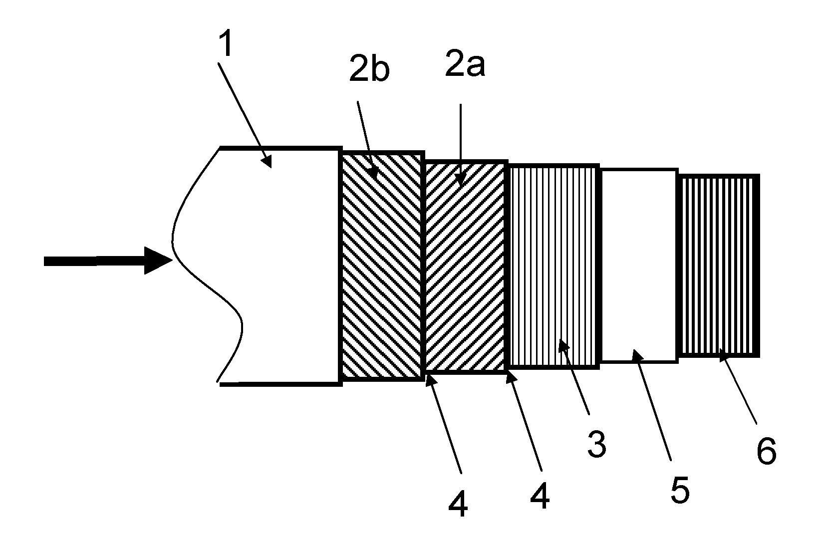
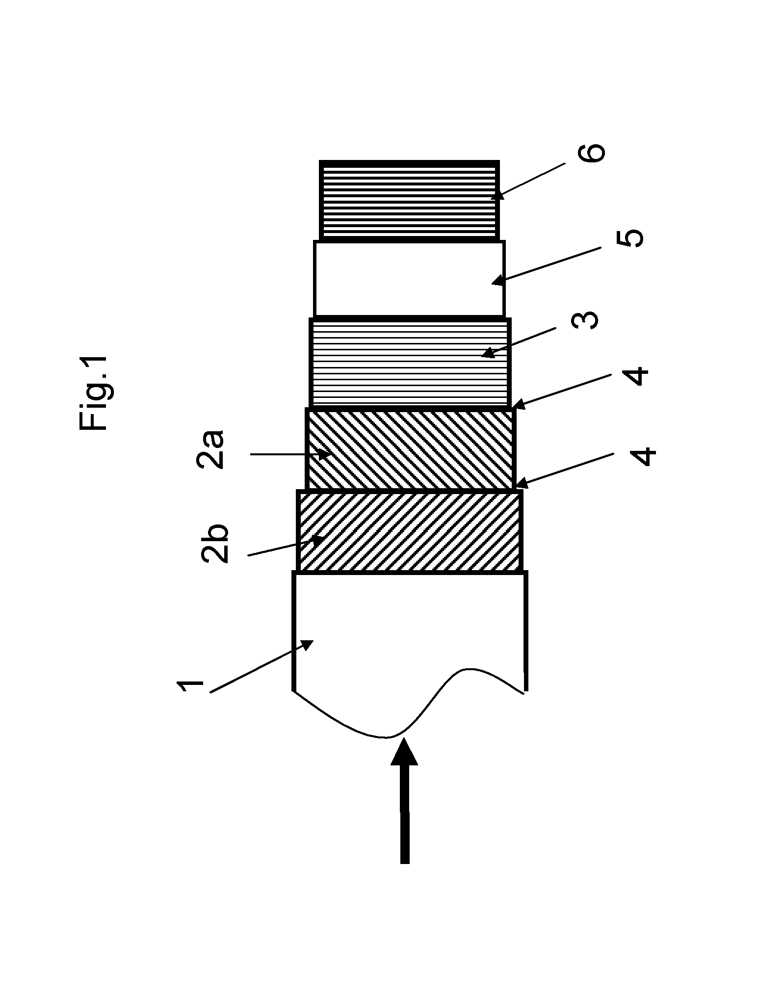
[0130]FIG. 1 is a schematic side view of a flexible unbonded pipe of the invention.

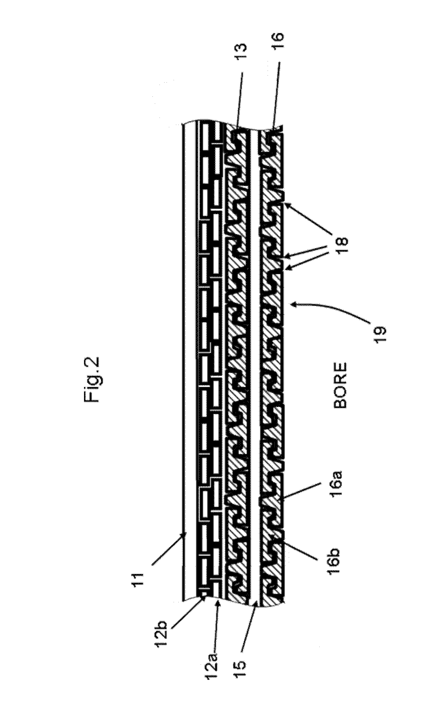
[0131]FIG. 2 is a cross-sectional view of along the length of a flexible pipe of the invention where the layers of the pipe can be seen.

[0132]FIG. 3a is a cross-sectional view of a first carcass, where the cross-sectional cut is taken in cross-section of the profiled elongate element.

[0133]FIG. 3b is a cross-sectional view of a second carcass, where the cross-sectional cut is taken in cross-section of the profiled elongate elements.

[0134]FIG. 4a is a cross-sectional view of a variation of the third carcass, where the cross-sectional cut is taken in cross-section of the profiled elongate element.

[0135]FIG. 4b is a cross-sectional view of a variation of the third carcass, where the cross-sectional cut is taken in cross-section of the profiled elongate element.

[0136]...


PUM


Abstract

An unbonded flexible pipe for transportation of fluids and comprising a tubular inner sealing sheath defining a bore. At least one armor layer surrounds the inner sealing sheath and a carcass is arranged in the bore to support the inner sealing sheath. The carcass comprises at least one profiled elongate element, which is helically wound to form directly and / or indirectly engaging elongate element windings along the length of the pipe. The carcass provides a quasi fluid permeable inner wall of the bore with discontinuities between successive turns of the wound elongate element(s). The discontinuities have an average width in the axial direction of the pipe which is about 3 mm or less when the pipe is in an unloaded and unbent condition, and the pipe can bend with a minimum bending radius of about 10 m or less in an unloaded condition.

Description

TECHNICAL FIELD[0001]The invention relates to a flexible pipe for transportation of fluids in offshore applications and in particular for transportation of gas containing fluids such as hydrocarbons.BACKGROUND ART[0002]Flexible pipes of the present type for offshore transportation of fluids are well known in the art. Such pipes usually comprise an inner liner also often called an inner sealing sheath or an inner sheath, which forms a barrier against the outflow of the fluid which is conveyed through the pipe, and one or more armoring layers on the outer side of the inner liner (outer armoring layer(s)). An outer sheath may be provided with the object of forming a barrier against the ingress of fluids from the pipe surroundings to the armor layers.[0003]Typical unbonded flexible pipes are e.g. disclosed in WO0161232A1, U.S. Pat. No. 6,123,114, U.S. Pat. No. 6,085,799 and in Recommended Practice for Flexible Pipe, API, 17B, Fourth edition, July 2008, and in Specification for Unbonded ...

Claims


Application Information

Patent Timeline
Patent Type & Authority Applications(United States)
IPC IPC(8): F16L11/00
CPCF16L11/00F16L11/082F16L11/16
Inventor GUDME, JONASNIELSEN, KARSTEN GORM
Owner NAT OILWELL VARCO DENMARK
Learn More