
System and method for operating a precooler in an aircraft

a technology for operating systems and precoolers, which is applied in the direction of machines/engines, efficient propulsion technologies, and energy-saving board measures, etc. it can solve the problems of insufficient cooling of remaining precoolers, inability to cool enough hot bleed air, and failure of bleed ducts, etc., to increase the amount of cold air received and improve the performance of the precooler

Active Publication Date: 2014-01-02
AIRBUS CANADA LLP
View PDF4 Cites 53 Cited by
  • Summary
  • Abstract
  • Description
  • Claims
  • Application Information

AI Technical Summary

Benefits of technology

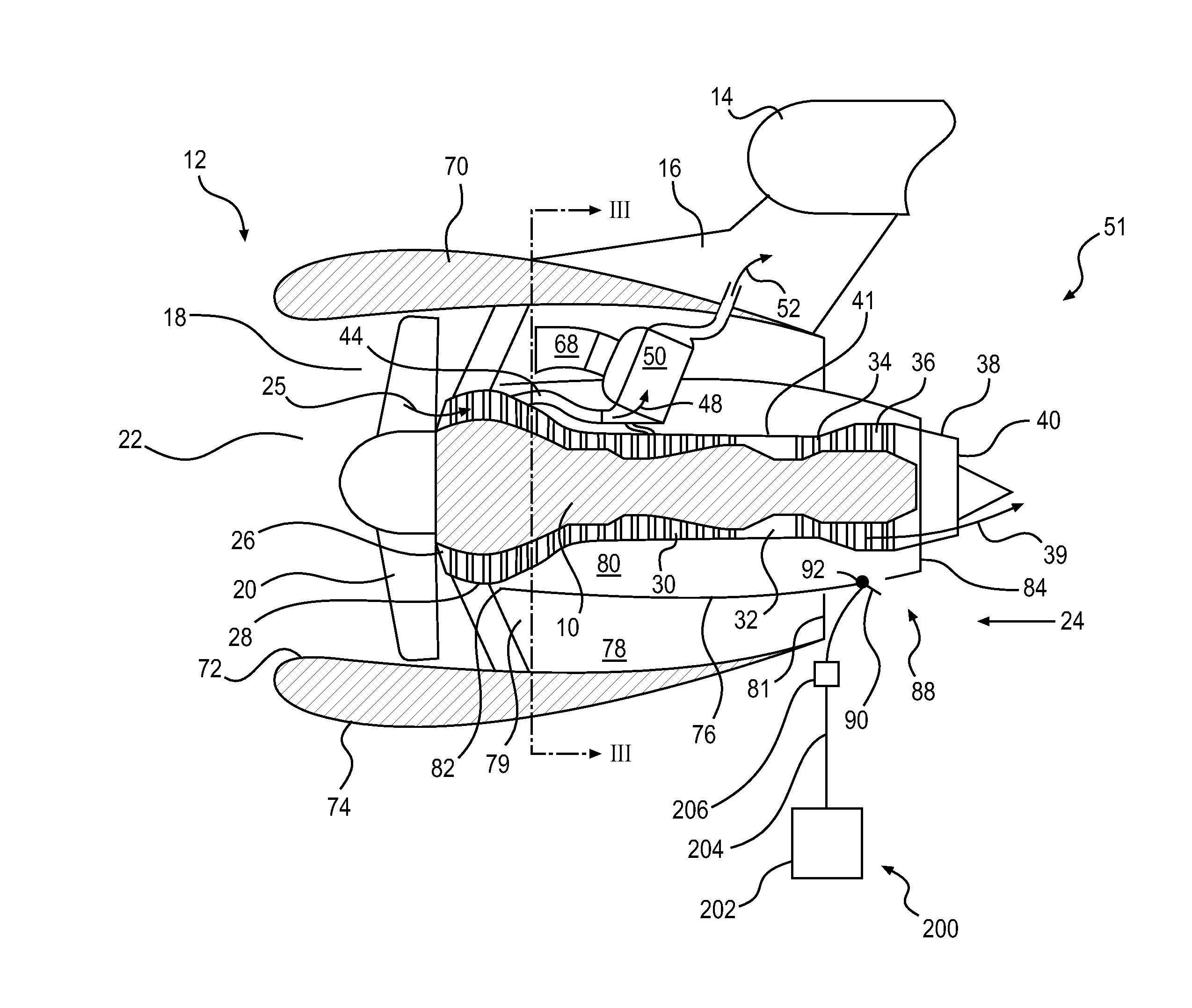
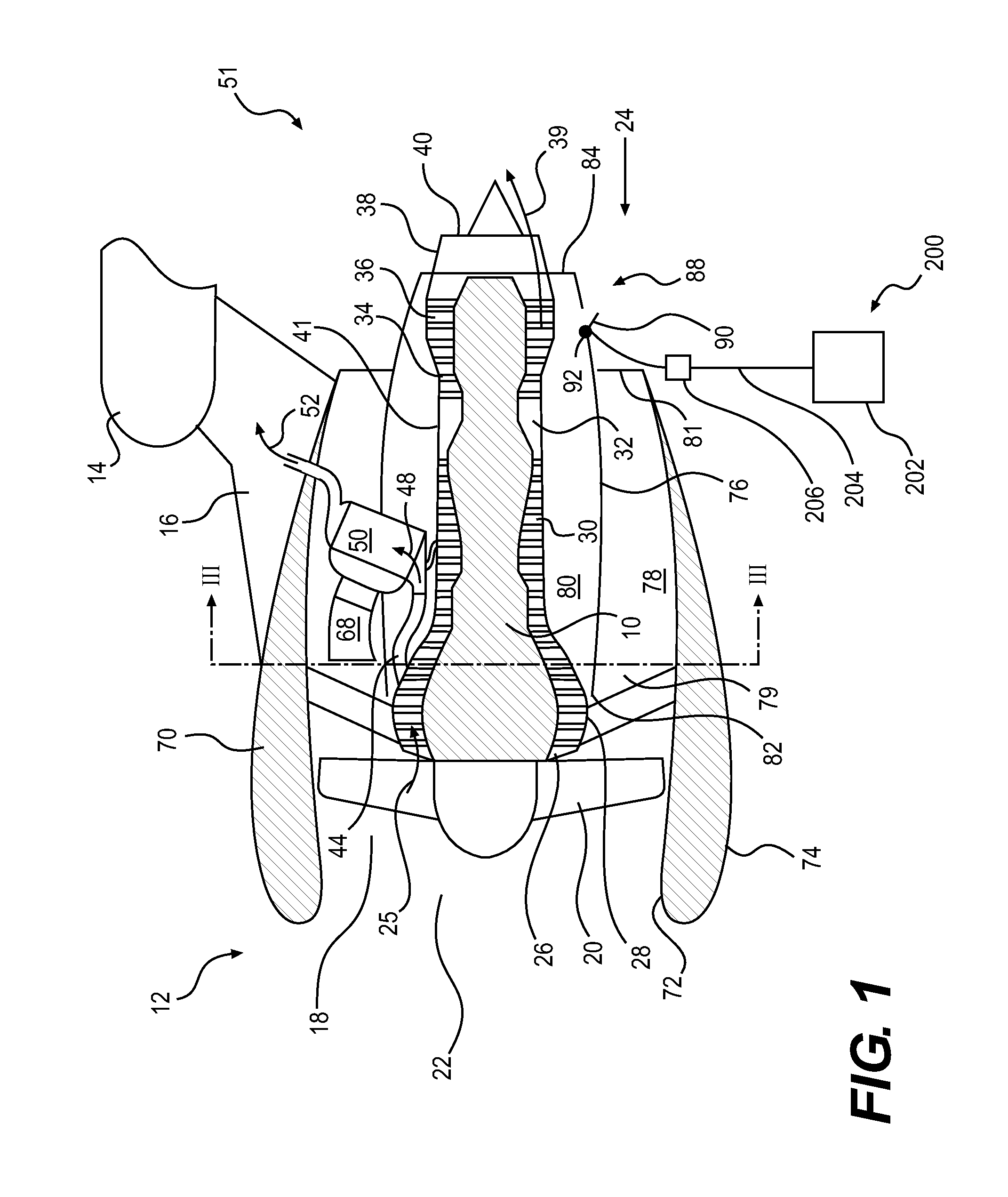
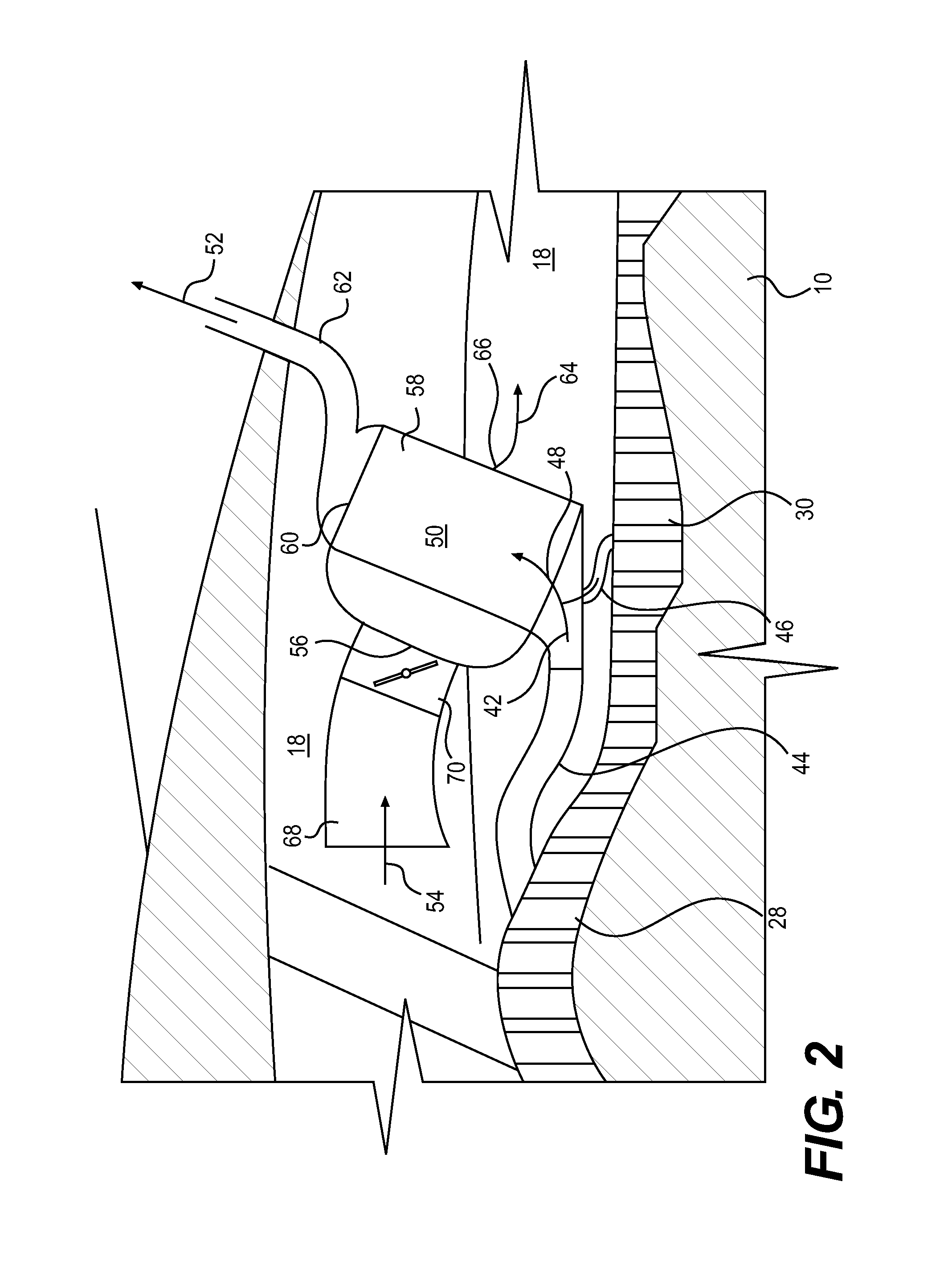
The present invention provides a system for improving the performance of a precooler, especially in situations where the precooler is operating below its normal level of performance. One embodiment includes an scoop to increase the amount of cold air received by the precooler. Another embodiment separates the air and bleed air passages to prevent intermixing during heat exchange. These improvements can increase the flow of cold air through the precooler and improve its performance, even in challenging conditions.

Problems solved by technology

One type of engine failure mentioned in the '506 Patent is a bleed duct failure.
With respect to precoolers, it has been found that, under certain operating conditions, the fan in the engine may not be able to provide enough cold air pressure to the precooler to enable all the onboard functions desired for the aircraft.
However, if one engine fails or one engine bleed system fails and the aircraft enters an ice condition, it is possible that the remaining precooler(s) may not be able to cool enough hot bleed air to supply both the HVAC system and the anti-icing system at the same time.
Naturally, where an aircraft changes course, the flight may be disrupted.
Moreover, the aircraft may be prevented from reaching its destination and may be required to land for maintenance.
However, a larger outlet may negatively affect aircraft performance, even during normal system operation, since core exhaust recovery is reduced.
A larger precooler, however, will add mass to the aircraft, will likely increase installation difficulty, and may further disrupt the flow of air within or around the engine.

Method used


Image

  • System and method for operating a precooler in an aircraft
  • System and method for operating a precooler in an aircraft
  • System and method for operating a precooler in an aircraft

Examples


Embodiment Construction

[0066]While the invention will be described in conjunction with specific embodiments. It should be understood that the discussion of any one, particular embodiment is not intended to be limiting of the scope of the present invention. To the contrary, the specific, enumerated embodiments are intended to illustrate a wide variety of alternatives, modifications, and equivalents that should be apparent to those of ordinary skill in the art. The present invention is intended to encompass any such alternatives, modifications, and equivalents as if discussed herein.

[0067]In the following description, the same numerical references are intended to refer to similar elements. The re-use of reference numerals for different embodiments of the present invention is intended to simplify the discussion of the present invention. It should not be inferred, therefore, that the re-use of reference numbers is intended to convey that the associated structure is identical to any other described embodiment....


PUM


Abstract

An aircraft engine includes a precooler disposed within a nacelle. The precooler defines an ambient air passage and a bleed air passage. Air passes through the precooler from an ambient air inlet to an ambient air outlet. Bleed air passes through the precooler from a bleed air inlet to a bleed air outlet. Heat is transferred between the air and the bleed air via heat exchange within the precooler. At least one pressure relief door disposed proximate to the air outlet of the engine. A controller is operatively connected to the pressure relief door. The controller at least opens the pressure relief door based on a demand for increased flow of air through the ambient air passage.

Description

CROSS-REFERENCE TO RELATED APPLICATION(S) [0001]This Patent Cooperation Treaty Patent Application relies for priority on U.S. Provisional Patent Application Ser. No. 61 / 453,657, filed on Mar. 17, 2011, the content of which is incorporated herein by reference.FIELD OF THE INVENTION [0002]The present invention relates to a system and method for operating a precooler in an aircraft. In particular, the present invention encompasses an apparatus and method for temporarily increasing the performance of a precooler in an aircraft.DESCRIPTION OF RELATED ART [0003]It is known to bleed hot, compressed air generated by an aircraft engine and provide that compressed air to equipment on the aircraft to perform certain onboard functions.[0004]Specifically, it is known to siphon hot, compressed air (also referred to as “bleed air”) from an aircraft engine so that the hot air may be used for aircraft functions outside of the aircraft engine. For example, the bleed air may be used in an aircraft's h...

Claims


Application Information

Patent Timeline
Patent Type & Authority Applications(United States)
IPC IPC(8): F02C7/00
CPCF02C7/00B64D13/08B64D33/10B64D2013/0618F01D25/02F01D25/14F02C9/18F02K1/822F02K3/06F02K3/075F02K3/115F02C6/08F02C7/14Y02T50/50Y02T50/40Y02T50/60
Inventor BROUSSEAU, JEANAFRIANTO, SIGITHAMEL, REMIDESILETS, VALERIE
Owner AIRBUS CANADA LLP
Learn More