Optimal Pre-Load for Floating Mass Transducers

a technology of floating mass transducers and preload, which is applied in the field of medical implants, can solve the problems of causing the patient to unable to produce, and the patient can be placed in a worsening position

Active Publication Date: 2013-12-26
MED EL ELEKTROMEDIZINISCHE GERAETE GMBH
View PDF1 Cites 22 Cited by
  • Summary
  • Abstract
  • Description
  • Claims
  • Application Information

AI Technical Summary

Benefits of technology

The present invention provides a middle ear implant arrangement for converting electrical stimulation signals into mechanical stimulation signals. The arrangement includes a cochlear engagement member at the inner end of the transducer for coupling the mechanical stimulation signal to an outer cochlear surface of a recipient patient. A transducer loading structure is used for releasably engaging the transducer and includes a center spring structure that expands along a central spring axis to develop a spring force between the fixed anatomical structure and the outer end of the transducer. The arrangement has advantages over previous designs and can improve the response and stability of the implant.

Problems solved by technology

Middle ear implants using electromagnetic transducers can present some problems.
Disarticulation deprives the patient of any residual hearing he or she may have had prior to surgery, placing the patient in a worsened position if the implanted device is later found to be ineffective in improving the patient's hearing.
But this approach very much depends on the exact execution of the filling of fascia and yields non-reproducible results.
And either too much or too little exerted pressure on the membrane yields a distorted acoustic signal as perceived by the patient.

Method used


Image

  • Optimal Pre-Load for Floating Mass Transducers
  • Optimal Pre-Load for Floating Mass Transducers
  • Optimal Pre-Load for Floating Mass Transducers

Examples


Embodiment Construction

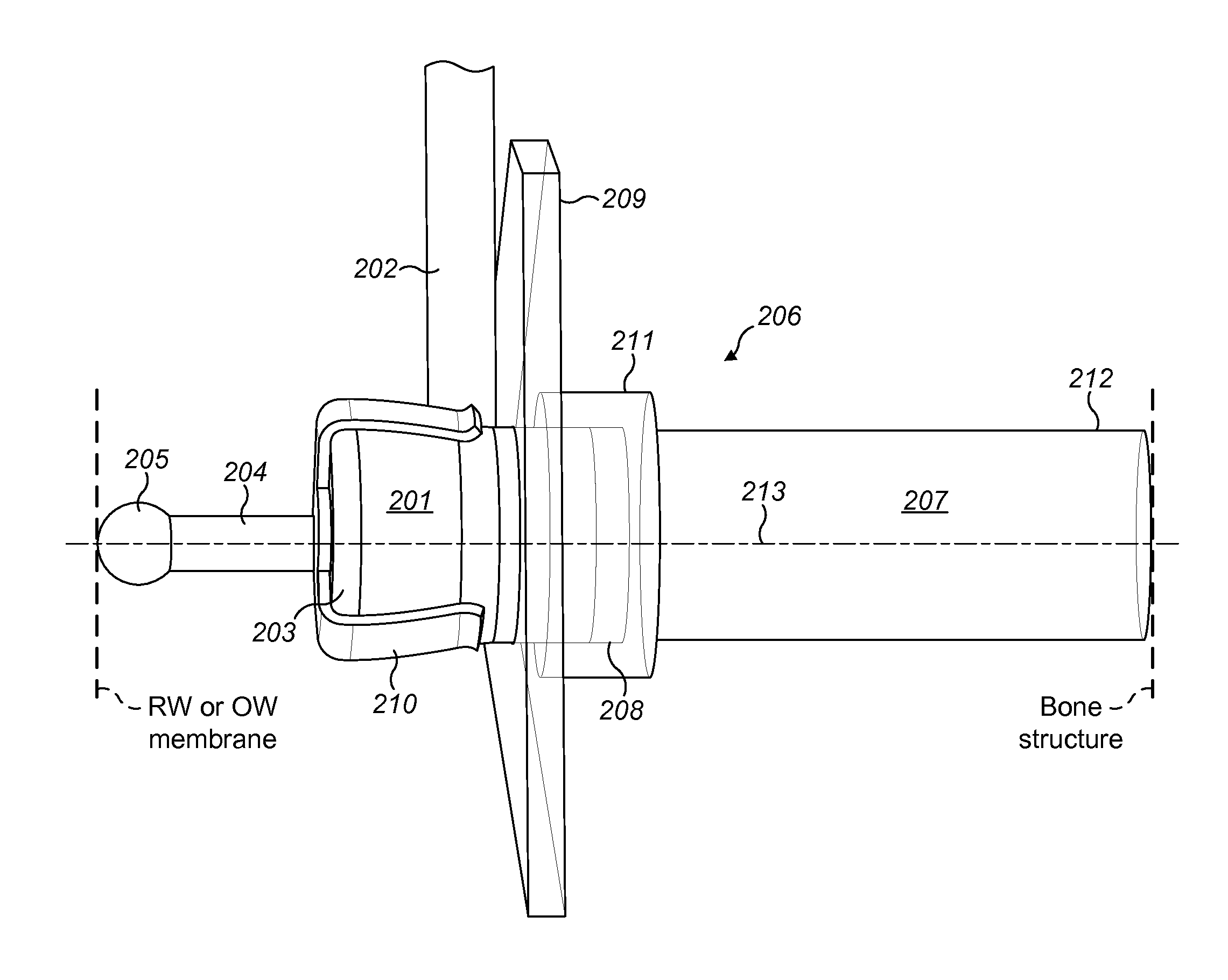
[0019]Various embodiments of the present invention are directed to a middle ear implant arrangement based on a loading structure for a hearing implant transducer that is adapted to develop a spring force that presses one end of the electromechanical transducer to firmly engage it against an outer surface of the implant patient's cochlea.

[0020]FIG. 2 shows one specific embodiment where an implantable electromechanical transducer 201 such as a floating mass transducer converts an electrical stimulation signal input from FMT signal lead 202 into a corresponding mechanical stimulation signal output. The transducer 201 has a cylindrical shape with an inner end 203 and an outer end 208. A cochlea engagement member 204 at the inner end 203 of the electromechanical transducer 201 has an engagement surface 205 for coupling the mechanical stimulation signal to an outer cochlear surface of a recipient patient, for example, the round window or oval window membrane.

[0021]A transducer loading str...


PUM


Abstract

A middle ear implant arrangement is described which includes an implantable electromechanical transducer with an inner end and an outer end, for converting an input electrical stimulation signal into a corresponding output mechanical stimulation signal. A cochlear engagement member at the inner end of the transducer has a cochlear engagement surface for coupling the mechanical stimulation signal to an outer cochlear surface of a recipient patient. A transducer loading structure has: i. an inner end adapted to releasably engage the transducer, ii. an outer end elongated along a central end axis for engaging a fixed anatomical structure within the middle ear of the recipient patient, and iii. a center spring structure connecting the inner end and the outer end and adapted to expand along a central spring axis to develop a spring force between the fixed anatomical structure and the outer end of the transducer.

Description

[0001]This application claims priority from U.S. Provisional Patent Application 61 / 663,788, filed Jun. 25, 2012, which is incorporated herein by reference.TECHNICAL FIELD[0002]The present invention relates to medical implants, and more specifically to a novel ossicular prosthesis arrangement.BACKGROUND ART[0003]A normal ear transmits sounds as shown in FIG. 1 through the outer ear 101 to the tympanic membrane (eardrum) 102, which moves the ossicles of the middle ear 103 (malleus, incus, and stapes) that vibrate the oval window and round window openings of the cochlea 104. The cochlea 104 is a long narrow duct wound spirally about its axis for approximately two and a half turns. It includes an upper channel known as the scala vestibuli and a lower channel known as the scala tympani, which are connected by the cochlear duct. The cochlea 104 forms an upright spiraling cone with a center called the modiolar where the spiral ganglion cells of the acoustic nerve 105 reside. In response to...

Claims


Application Information

Patent Timeline
Patent Type & Authority Applications(United States)
IPC IPC(8): H04R25/00
CPCH04R25/606
Inventor SANTEK, MICHAEL
Owner MED EL ELEKTROMEDIZINISCHE GERAETE GMBH
Why Eureka
Try Eureka