Anti-Detachment Chainwheel having Forced Recessed Face at Chain Tooth Root Portion

a chain tooth root and anti-detachment technology, which is applied in the direction of gearing, gearing elements, hoisting equipment, etc., can solve the problem that the chain is even more likely to be detached

Inactive Publication Date: 2013-12-26
YANG TAI HER
View PDF8 Cites 5 Cited by
  • Summary
  • Abstract
  • Description
  • Claims
  • Application Information

AI Technical Summary

Benefits of technology

The present invention is about a chainwheel that prevents a chain from detaching easily. It has a special part at the root of each tooth where a roller can be tightly engaged. This improves the chain's stability and prevents it from coming off.

Problems solved by technology

A conventional chainwheel is often utilized for bidirectional forced transmission, and gear teeth are formed in a symmetrical structure; for smoothly guiding the chain into the chainwheel, a symmetrical chevron angled tooth face (103) having a tooth peak (105) at outer side and a wider chain tooth root portion at inner side has to be formed between the tooth shape and the chain roller (110) sleeved on a chain connecting pivot shaft (109) installed between lateral connecting sheets at each segment of the chain; however, one major shortage thereof is that when the chainwheel is driven by the chain, the oblique face formed on the chain tooth has a constant tendency of forcing the chainwheel to be outwardly detached, especially when less quantity of chain tooth being engaged with the chain, or when the chain being driven to swing towards the centrifugal direction under the situation of high speed transmission and altering load, the chain is even more likely to be detached.

Method used


Image

  • Anti-Detachment Chainwheel having Forced Recessed Face at Chain Tooth Root Portion
  • Anti-Detachment Chainwheel having Forced Recessed Face at Chain Tooth Root Portion
  • Anti-Detachment Chainwheel having Forced Recessed Face at Chain Tooth Root Portion

Examples


Embodiment Construction

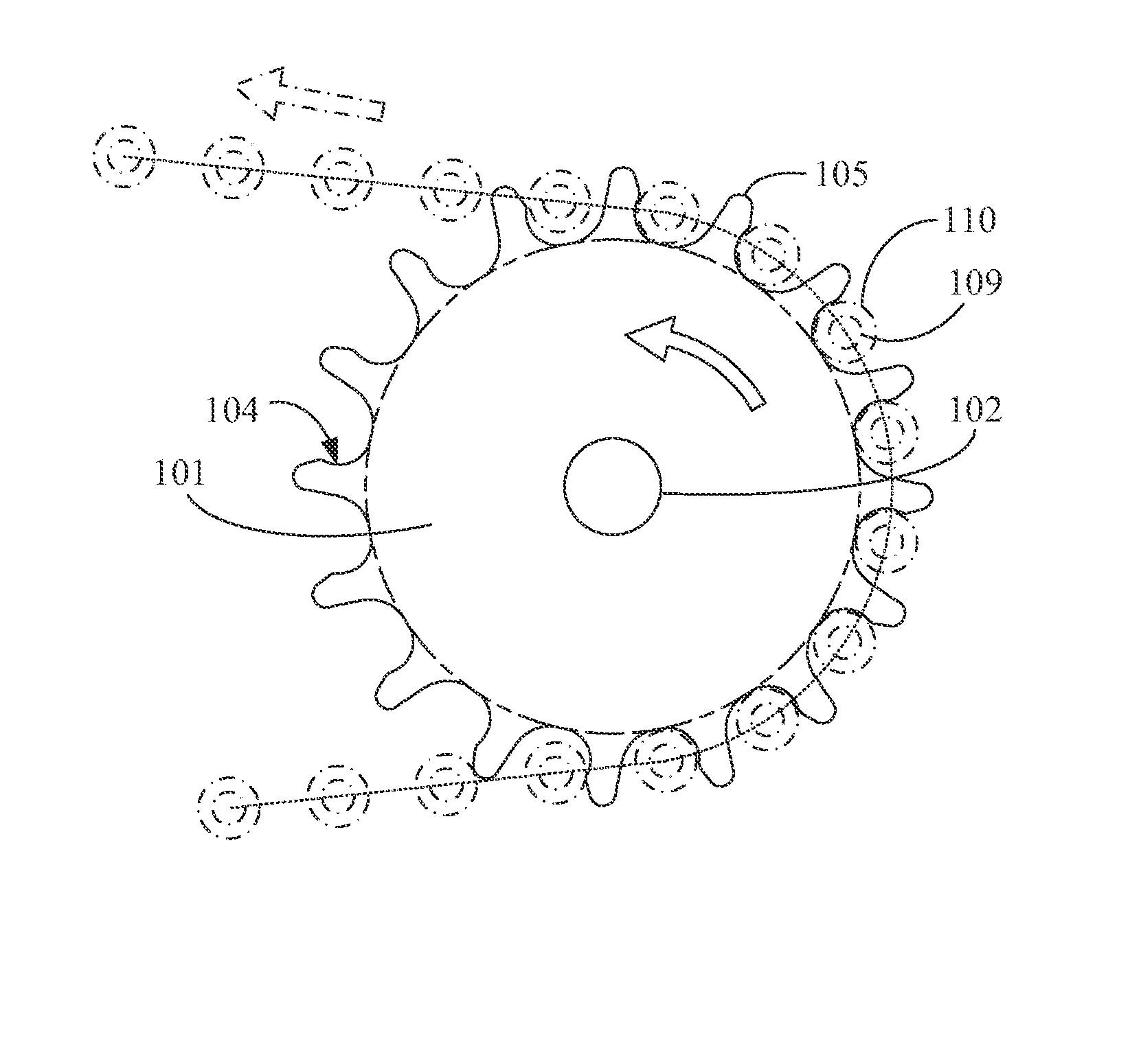
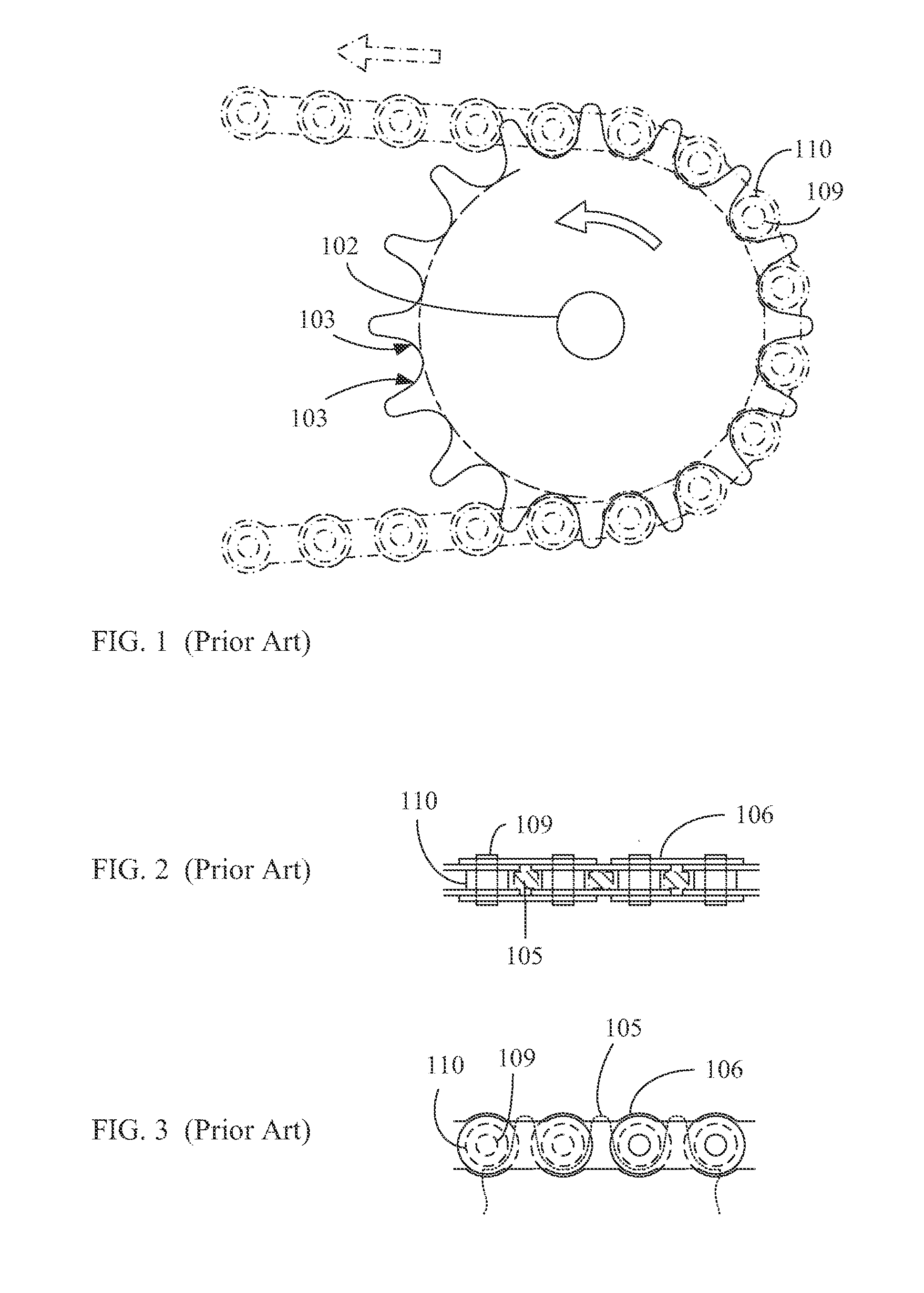
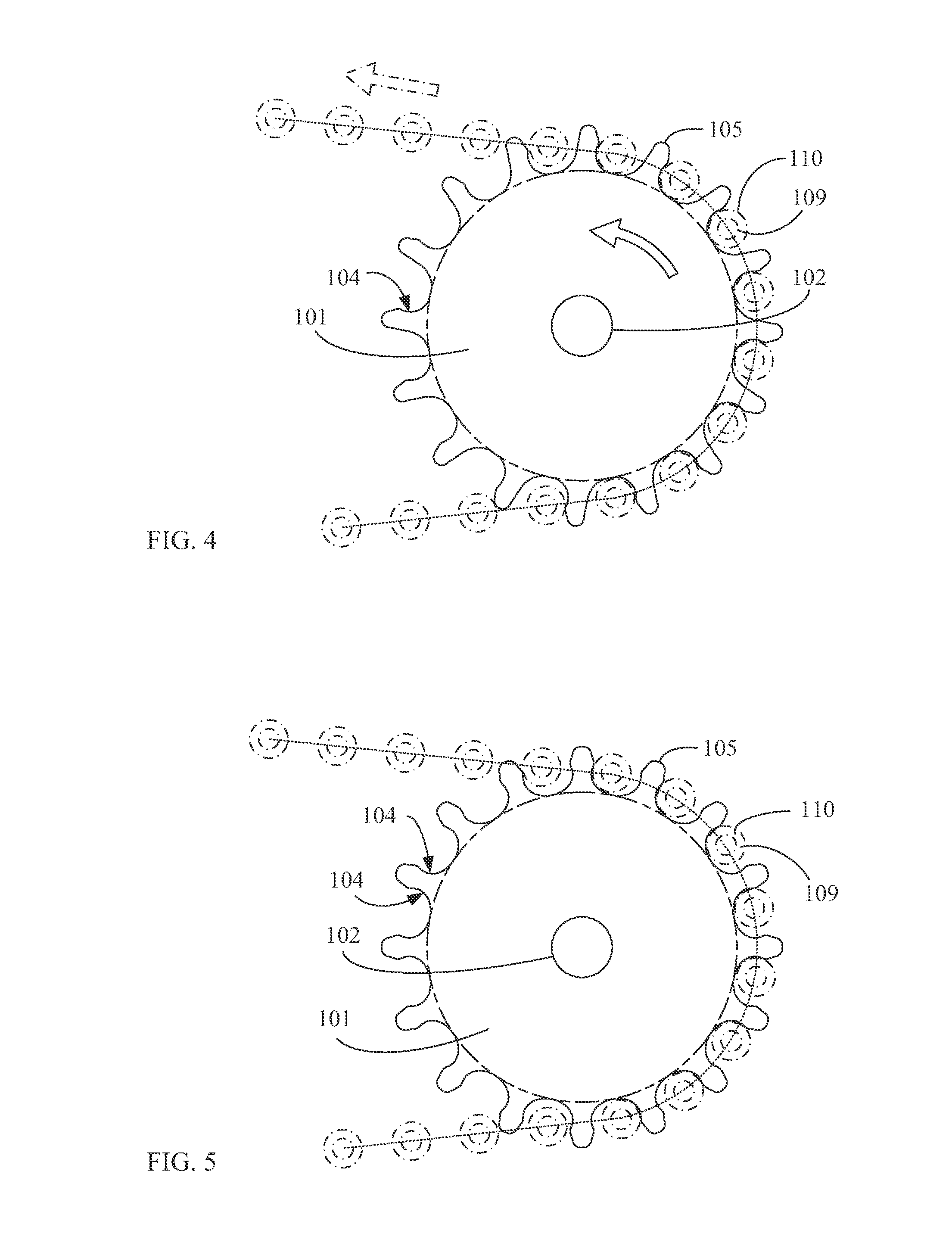
[0025]A conventional chainwheel is often utilized for bidirectional forced transmission, and gear teeth are formed in a symmetrical structure; for smoothly guiding the chain into the chainwheel, a symmetrical chevron angled tooth face (103) having a tooth peak (105) at outer side and a wider chain tooth root portion at inner side has to be formed between the tooth shape and the chain roller (110) sleeved on a chain connecting pivot shaft (109) installed between lateral connecting sheets at each segment of the chain; however, one major shortage thereof is that when the chainwheel is driven by the chain, the oblique face formed on the chain tooth has a constant tendency of forcing the chainwheel to be outwardly detached, especially when less quantity of chain tooth being engaged with the chain, or when the chain being driven to swing towards the centrifugal direction under the situation of high speed transmission and altering load, the chain is even more likely to be detached;

[0026]Th...


PUM


Abstract

The present invention provides a novel anti-detachment chainwheel having forced recessed face at chain tooth root portion, in which a chain roller (110) sleeved on a chain connecting pivot shaft (109) can be tightened engaged at a forced recessed face at chain tooth root portion (104) while the chainwheel being driven by a chain, thereby improving the shortage of the chain being easily detached from the chainwheel.

Description

BACKGROUND OF THE INVENTION[0001](a) Field of the Invention[0002]The present invention provides a novel anti-detachment chainwheel having forced recessed face at chain tooth root portion, in which a chain roller (110) sleeved on a chain connecting pivot shaft (109) can be tightened engaged at a forced recessed face at chain tooth root portion (104) while the chainwheel being driven by a chain, thereby improving the shortage of the chain being easily detached from the chainwheel; the anti-detachment chainwheel having forced recessed face at chain tooth root portion provided by the present invention includes unidirectional transmission and bidirectional transmission structures.[0003](b) Description of the Prior Art[0004]A conventional chainwheel is often utilized for bidirectional forced transmission, and gear teeth are formed in a symmetrical structure; for smoothly guiding the chain into the chainwheel, a symmetrical chevron angled tooth face (103) having a tooth peak (105) at outer...

Claims


Application Information

Patent Timeline
IPC IPC(8): F16H55/17
CPCF16H55/30F16H2035/001F16H2035/003
Inventor YANG, TAI-HER
Owner YANG TAI HER
Why Eureka
Try Eureka