Power conversion apparatus
a technology of power conversion apparatus and power transformer, which is applied in the direction of electric variable regulation, process and machine control, instruments, etc., can solve the problem of increasing the amplitude of the ripple of the alternating current output of the power conversion apparatus
- Summary
- Abstract
- Description
- Claims
- Application Information
AI Technical Summary
Benefits of technology
Problems solved by technology
Method used
Image


Examples
first embodiment
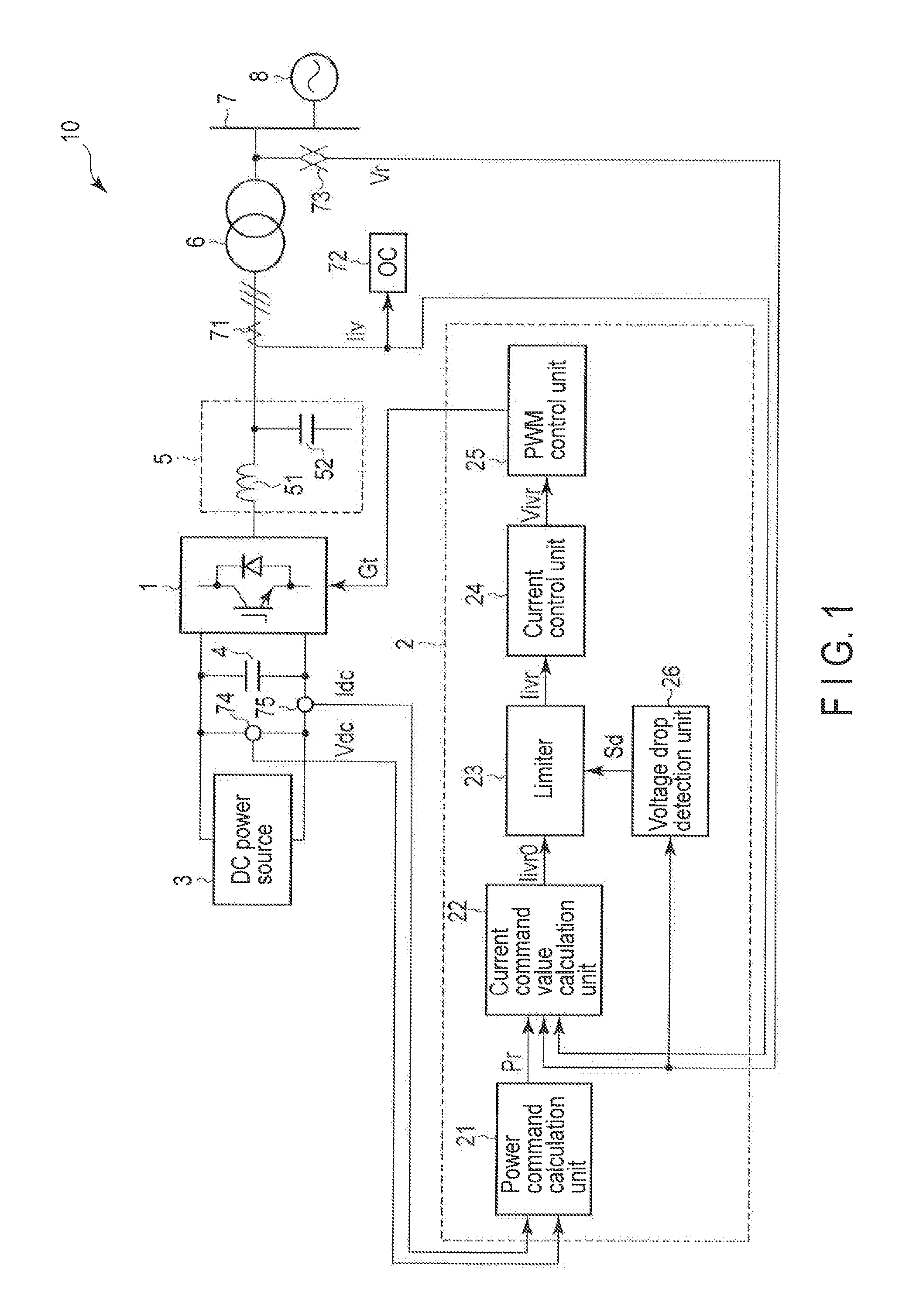
[0017]FIG. 1 is a block diagram showing a constitution of a dispersed generation system 10 to which a control apparatus 2 of an inverter 1 according to a first embodiment of the invention is applied. It is to be noted that the same parts as in the drawings are denoted with like reference signs to omit detailed description of the parts, and different parts will mainly be described. Also in the subsequent embodiments, repeated descriptions are similarly omitted.
[0018]The dispersed generation system 10 comprises the inverter 1, the control apparatus 2, a DC power source 3, a smoothing capacitor 4, an AC filter 5, an interconnection transformer 6, an AC current detector 71, an overcurrent relay 72, an AC voltage detector 73, and a DC voltage detector 74. The dispersed generation system 10 is a generation system which interconnects with an AC power system including a system bus 7 and an AC power source 8.
[0019]The DC power source 3 supplies a DC power to the inverter 1. The DC power sour...
second embodiment
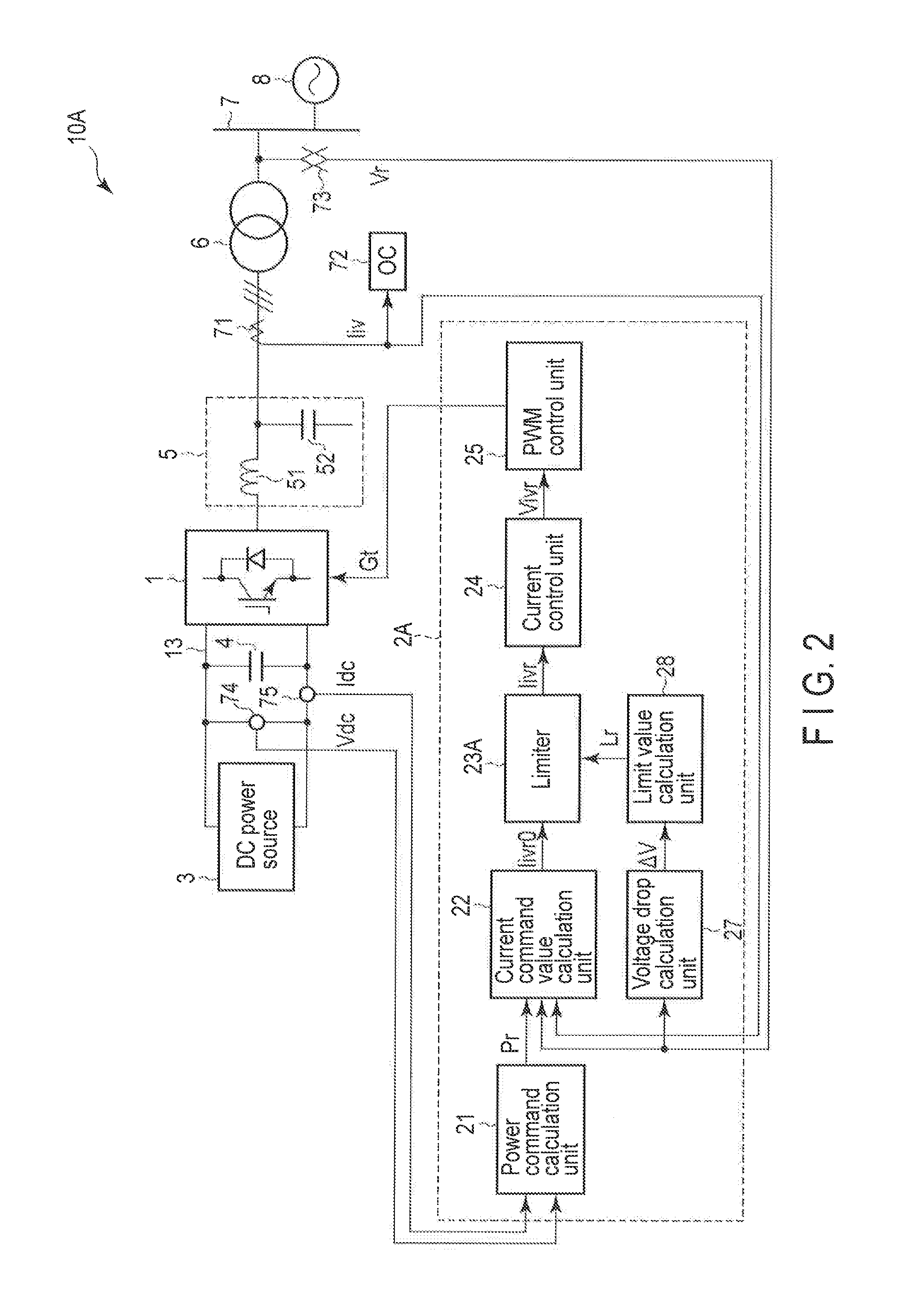
[0041]FIG. 2 is a block diagram showing a constitution of a dispersed generation system 10A to which a control apparatus 2A of an inverter 1 according to a second embodiment of the invention is applied.
[0042]The dispersed generation system 10A has a constitution where in the dispersed generation system 10 according to the first embodiment shown in FIG. 1, the control apparatus 2 is replaced with the control apparatus 2A. The other respects are similar to those of the dispersed generation system 10 according to the first embodiment.
[0043]The control apparatus 2A has a constitution where in the control apparatus 2 according to the first embodiment, the limiter 23 is replaced with a limiter 23A and the voltage drop detection unit 26 is replaced with a voltage drop calculation unit 27 and a limit value calculation unit 28. The other aspects are similar to those of the control apparatus 2 according to the first embodiment.
[0044]Into the voltage drop calculation unit 27, a system voltage ...
third embodiment
[0048]FIG. 3 is a block diagram showing a constitution of a dispersed generation system 10B to which a power conditioner 20 of a wind power generation system according to a third embodiment of the invention is applied.
[0049]The dispersed generation system 10B has a constitution where in the dispersed generation system 10 according to the first embodiment shown in FIG. 1, the control apparatus 2 is replaced with a control apparatus 2B, the DC power source 3 is replaced with a wind power generator 11 and a converter 12, and an AC current detector 76 is added. The power conditioner 20 comprises the inverter 1, the converter 12, the control apparatus 2B, the smoothing capacitor 4, and the AC filter 5. The other aspects are similar to those of the dispersed generation system 10 according to the first embodiment.
[0050]The wind power generator 11 is a generator to generate an AC power by use of wind power. The wind power generator 11 supplies the generated AC power to the power conditioner...
PUM
 Abstract
Description
Claims
Application Information
 - R&D
- Intellectual Property
- Life Sciences
- Materials
- Tech Scout
- Unparalleled Data Quality
- Higher Quality Content
- 60% Fewer Hallucinations
Browse by: Latest US Patents, China's latest patents, Technical Efficacy Thesaurus, Application Domain, Technology Topic, Popular Technical Reports.
© 2025 PatSnap. All rights reserved.Legal|Privacy policy|Modern Slavery Act Transparency Statement|Sitemap|About US| Contact US: help@patsnap.com