
Multi-level voltage regulator system and method

a voltage regulator and multi-level technology, applied in the direction of electric variable regulation, process and machine control, instruments, etc., can solve the problems of unfavorable pol converter output oscillation, limited “safe” regulation methods of prior-art converter architectures, and unpredictable output voltage (vout) performan

Active Publication Date: 2013-12-19
TDK LAMBDA CORP
View PDF6 Cites 40 Cited by
  • Summary
  • Abstract
  • Description
  • Claims
  • Application Information

AI Technical Summary

Benefits of technology

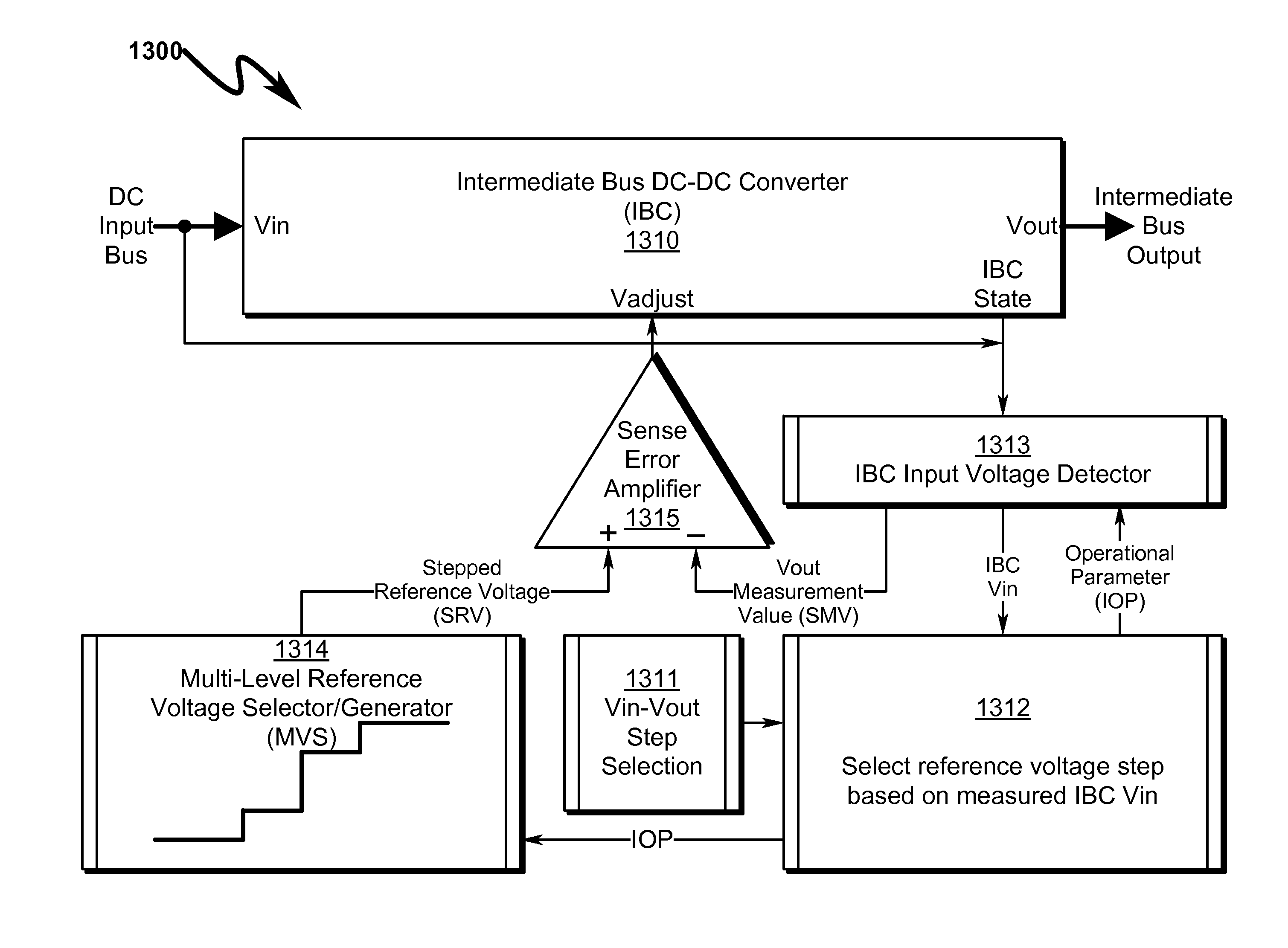
The patent describes a system and method for regulating voltage using multiple levels. This approach reduces the likelihood of instability in voltage levels and ensures reliable operation by keeping components at their maximum operating values. Overall, this technology helps to improve the stability and performance of voltage regulation in various applications.

Problems solved by technology

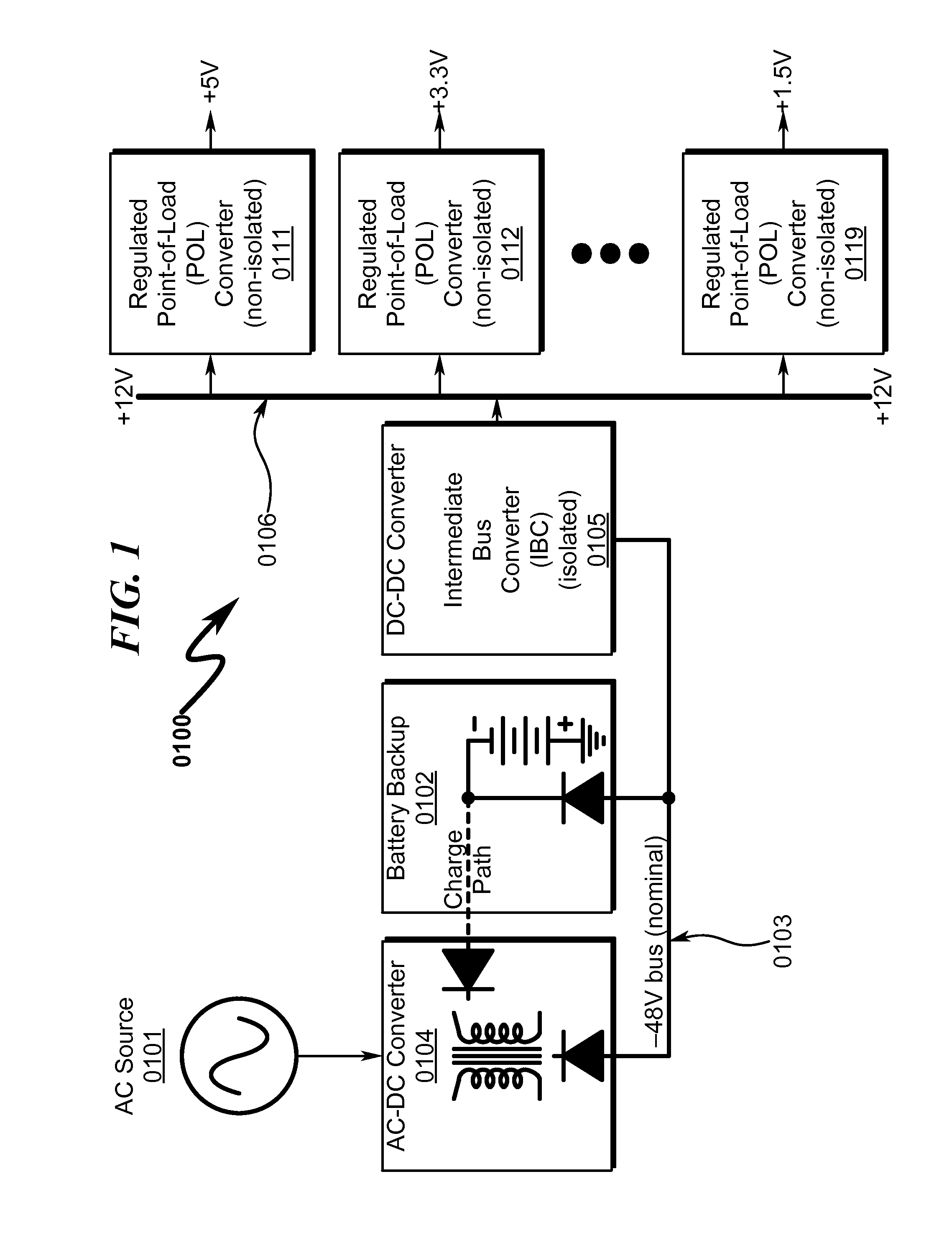
Unfortunately, some prior-art converter architectures have limited the “safe” regulation methods that can be used in the distributed power architecture with IBCs (0105) and POL converters (0111, 0112, 0119).
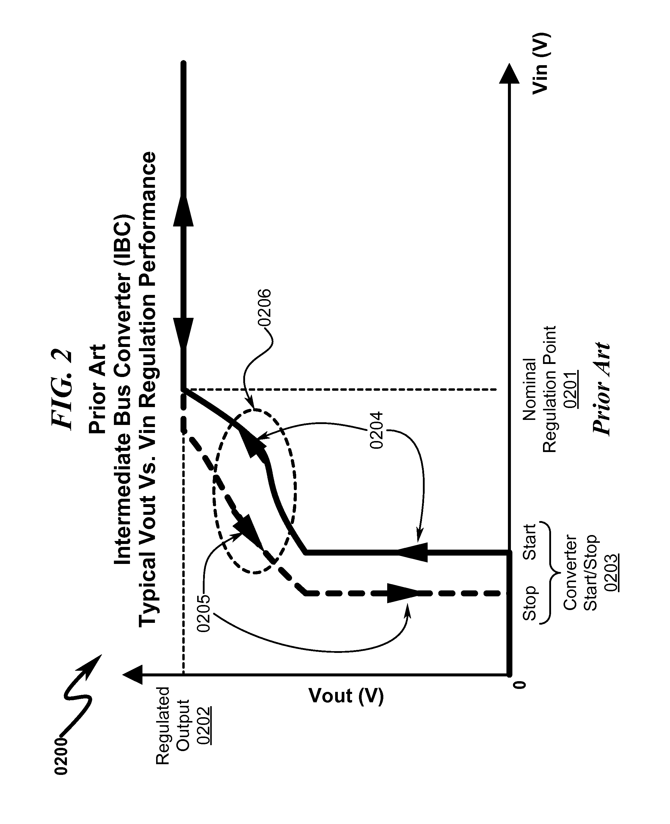
A significant issue in the performance of typical IBC converters is the unpredictable nature of output voltage (Vout) performance based on a variety of other parameters associated with the current IBC state.
The non-linear transition regions (0206) (from regulated to “loosely regulated” IBC output voltage) are particularly problematic since these regions can produce unpredictable behavior in attached POL regulators.
For example, these transition regions (0206) can result in undesirable oscillation of the POL converter output as the input to the POL varies from a regulated to a loosely regulated state (and vice-versa).
The critical point between the control loop full regulation and the control loop loosely regulated may also cause the IBC to be unstable due to a fixed frequency, peak-sensing current mode controlled IBC converter with duty cycle approaching 50% or higher.
As evidenced by the temperature samples depicted in the graphs of FIG. 3 (0300), FIG. 5 (0500), and FIG. 7 (0700), increases in temperature generally result in greater unpredictability in the operational stability of the IBC.

Method used


Image

  • Multi-level voltage regulator system and method
  • Multi-level voltage regulator system and method
  • Multi-level voltage regulator system and method

Examples


embodiment (

DETAILED EMBODIMENT (1500)

[0129]A more detailed example of a schematic implementation of the block diagram of FIG. 14 (1400) is generally depicted in FIG. 15 (1500) which illustrates a staircase two-level flat-line regulation circuit. An input voltage detection circuitry U1 with the hysteresis is used to detect Vin. The IBC Enable Signal is used to control Q2, which is connected in parallel with Vref line. When the Vin is below Vin(low) (or IBC(off) point for a two-level regulation circuit), the IBC is off, and the IBC Enable Signal will turn on Q2 to pull Vref line to zero volts. Note that this same enable signal may disable the PWM controller from generating any driving pulses (this feature is not shown in FIG. 16 (1600)). If Vin≧Vin (min) (or IBC Turn-on point), then the output of the input voltage detection circuit block U1 will be high to turn on Q3, and hence, disable Q1. When U1 is high, R12 connects to Vcc via R13, which adds a small current to R11 to raise its voltage at no...


PUM


Abstract

A multi-level voltage regulator system / method providing discrete regulation of a DC-DC intermediate bus converter (IBC) output voltage (Vout) is disclosed. The disclosed system / method allows IBC Vout to be regulated in discrete steps during periods where IBC input voltage (Vin) falls below nominal operating values. Rather than shutting down or degrading IBC Vout in an unpredictable non-linear fashion based on IBC input / loading, IBC Vout is regulated in fixed discrete steps, allowing IBC-connected point-of-load (POL) converters to obtain stable power input that is well-defined over IBC Vin. IBC operating parameters may define multi-dimensional operational state spaces of IBC Vout regulation that ensure optimum power flow to attached POLs while maintaining operational stability within the IBC regulator. Instabilities in IBC / POL performance across variations in IBC Vin, load transients, POL loading, and environmental variables may be prevented using Vin voltage step hysteresis.

Description

CROSS REFERENCE TO RELATED APPLICATIONSCIP Application[0001]This patent application is a continuation-in-part (CIP) of parent U.S. Utility patent application for “LOOSELY REGULATED FEEDBACK CONTROL FOR HIGH EFFICIENCY ISOLATED DC-DC CONVERTERS”, Ser. No. 13 / 070,959, docket AINNO.0127, filed electronically with the USPTO on Mar. 24, 2011 with EFS ID 9732749 and Confirmation Number 3088.UTILITY PATENT APPLICATIONS[0002]Applicant claims benefit pursuant to 35 U.S.C. §120 and hereby incorporates by reference U.S. Utility patent application for “LOOSELY REGULATED FEEDBACK CONTROL FOR HIGH EFFICIENCY ISOLATED DC-DC CONVERTERS”, Ser. No. 13 / 070,959, docket AINNO.0127, filed electronically with the USPTO on Mar. 24, 2011 with EFS ID 9732749 and Confirmation Number 3088.[0003]Applicant claims benefit pursuant to 35 U.S.C. §120 and hereby incorporates by reference U.S. Utility patent application for “LOOSELY REGULATED FEEDBACK CONTROL FOR HIGH EFFICIENCY ISOLATED DC-DC CONVERTERS”, Ser. No. 1...

Claims


Application Information

Patent Timeline
Patent Type & Authority Applications(United States)
IPC IPC(8): H02M3/04
CPCH02M3/04H02M3/33592H02M3/3378G05F1/10Y02B70/10H02M1/0022H02M1/008H02M3/08
Inventor HE, JINBOYLAN, JEFFREY JOHN
Owner TDK LAMBDA CORP
Learn More