
Control switch for use in a working machine

a control switch and working machine technology, applied in the direction of mechanical control devices, manual control with single control member, instruments, etc., can solve the problems of not always convenient for the driver to feel the feedback of the buttons, and the control of the working machine is a complex process. , to achieve the effect of good feedback feeling of the control switch

Inactive Publication Date: 2013-12-19
JOHN DEERE FORESTRY OY
View PDF14 Cites 10 Cited by
  • Summary
  • Abstract
  • Description
  • Claims
  • Application Information

AI Technical Summary

Benefits of technology

The control switch described in this patent reduces the problems associated with other control switches. It has a good feedback feel and works well in a working machine. It consists of a switch and a selection button, which can be used together or separately. This switch has more functions than other buttons, making it more versatile. Overall, this control switch solves problems and provides better control signals for working machines.

Problems solved by technology

In particular, the control of working machines is a complex process.
Furthermore, the feedback feeling of the buttons is not always convenient for the driver.

Method used


Image

  • Control switch for use in a working machine
  • Control switch for use in a working machine
  • Control switch for use in a working machine

Examples


Embodiment Construction

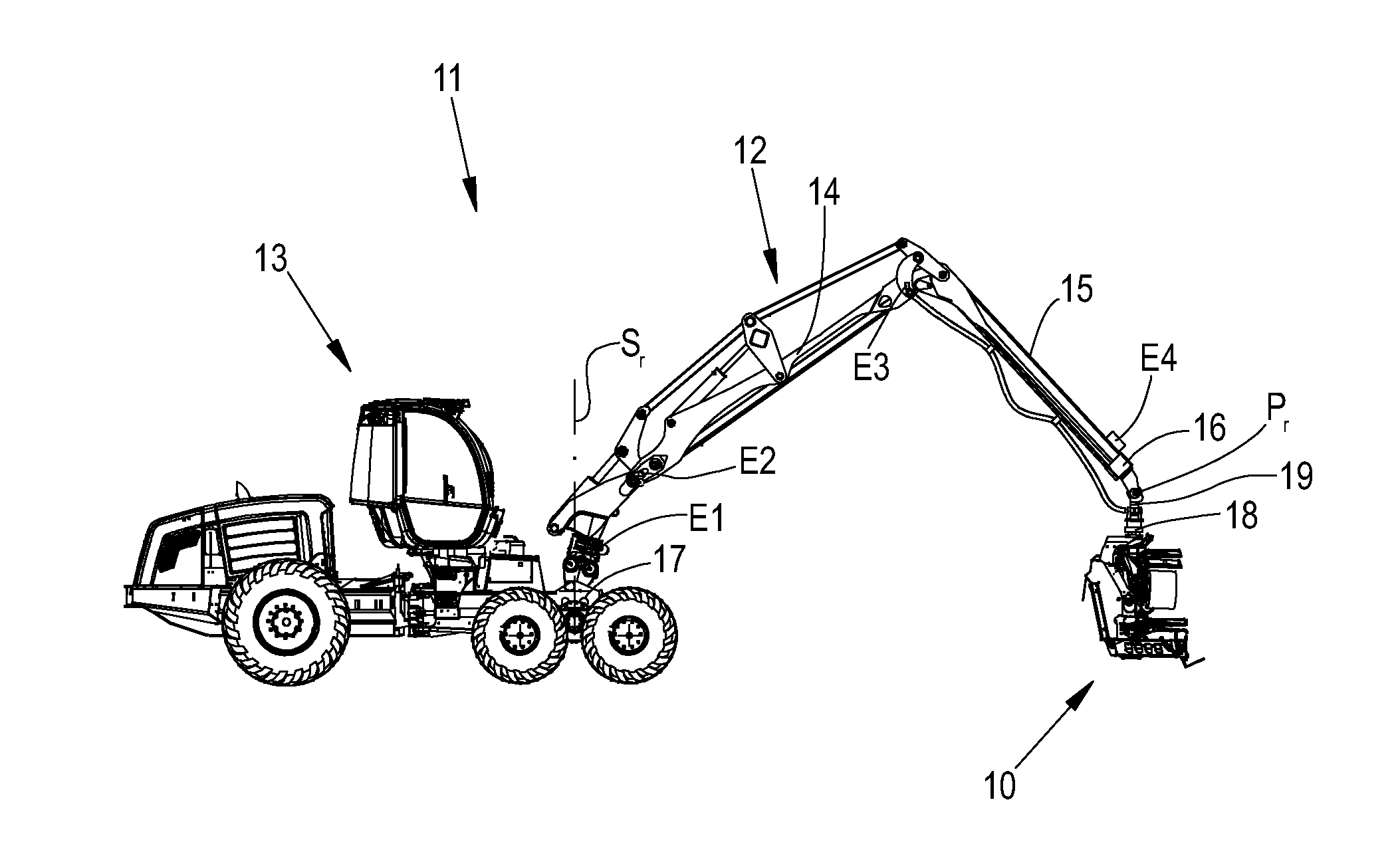
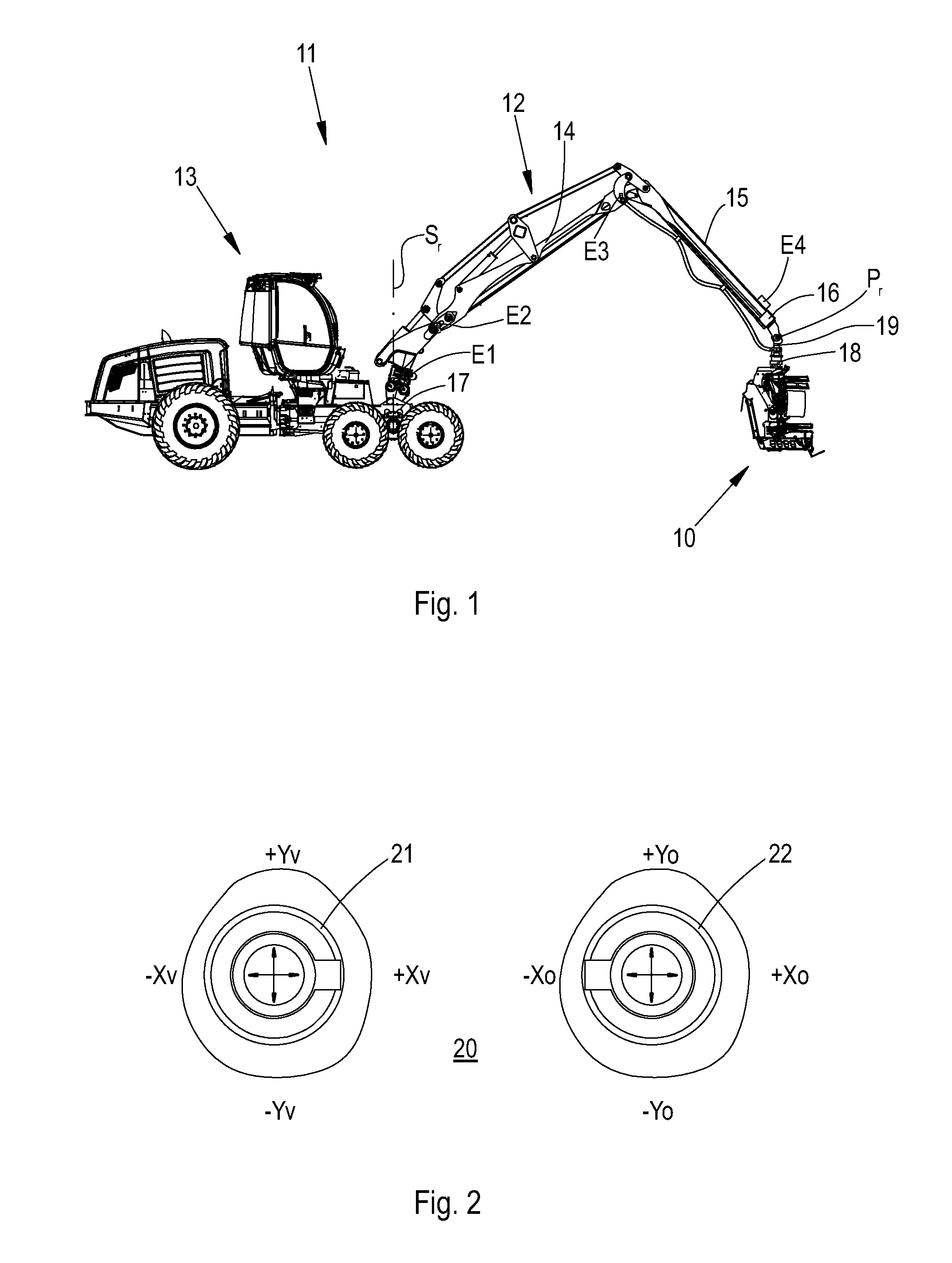
[0017]FIG. 1 shows a working machine 11. The working machine 11 comprises a base machine 13. The working machine 11 further comprises a traverser 17 and a boom assembly 12 mounted on the traverser 17. The boom assembly 12 comprises booms, for example a hoist boom 14, a stick boom 15, and an extension boom 16. A rotating device 18, i.e. a rotator, is provided at the end Pr of the boom assembly 12. A tilting device 19, i.e. a tilter, is provided at the end Pr of the boom assembly 12. An implement 10 is connected to the rotator 18. At least one of the following is configured to be controlled: the base machine 13, the boom assembly, the traverser 17, the rotator 18, the tilter 19, and the implement 10. The working machine 11 of FIG. 1 is of the forest machine type, more precisely a harvester, for felling, delimbing and cross-cutting trees in a forest to logs of suitable length. In the working machine shown in the figure, the implement 10 is a harvester head. The harvester can be used fo...


PUM


Abstract

A control switch to be used in a working machine comprises a switch arranged to be in a position which can be selected from at least two positions, and a selection button which is arranged to be in a state which can be selected from two states. The switch of the control switch is of a rocker switch type, the selection button is integrated in the control switch, and the selection button is arranged to be used in combination with or independently of the rocker switch, wherein the control switch can be used for giving at least four different control signals. A control unit comprises said control switch and a stick-like control lever. A working machine comprises said control switch or said control unit.

Description

FIELD[0001]The present disclosure relates to control devices. In particular, the present disclosure relates to control devices for vehicles. The present disclosure relates particularly to control devices for working machines, such as forest machines.BACKGROUND[0002]Vehicles, such as working machines, are controlled by control devices. In this description, a working machine refers to devices which are configured to be movable, such as earth moving machines, stump pullers, tractors, tractor excavators, excavator loaders, mini loaders, wheel loaders, and forest machines, which are not only movable but also configured to perform other functions controlled by the driver. Such functions are described, among other things, by the above-mentioned designations of the working machines.[0003]A steering wheel is known as a control device for vehicles. The steering wheel may also comprise integrated buttons for controlling other devices of the vehicle, such as a vehicle radio. For example, a stee...

Claims


Application Information

Patent Timeline
Patent Type & Authority Applications(United States)
IPC IPC(8): G05G1/01
CPCG05G1/01G05G1/02G05G1/04G05G9/04788H01H23/14H01H23/30H01H25/008Y10T74/20372A01G23/003G05G13/00H01H3/12A01G23/00
Inventor PAAKKINEN, MARKO J.TAINIO, MIKKO
Owner JOHN DEERE FORESTRY OY
Learn More