Combinational chassis featuring heat dissipation

Active Publication Date: 2013-12-12
TRUSTED SOLUTIONS CORP
View PDF17 Cites 15 Cited by
  • Summary
  • Abstract
  • Description
  • Claims
  • Application Information

AI Technical Summary

Benefits of technology

The invention provides a heat-dissipating chassis that is space-efficient and can be expanded for flexible use. It optimizes space allocation and enhances heat dissipation, resulting in improved performance and increased utilization of available space.

Problems solved by technology

Existing electronic equipment often have high-performance components or devices to work with and thus features heat dissipation; for example, important components installed in a computer, such as central processing unit (CPU), north and south bridge chips, hard drives and the like will produce heat when operating, and if the temperature of the component is too high, it will affect the performance of computer and will cause the computer to shutdown or impair the computer's service life.
However, some particular computer systems are not provided with the fans, such as PC barebones that features proper heat dissipation instead of fan installation for simplifying the physical volume and space of the computer.
However, to achieve the function of heat dissipation, the heat-dissipation fin must be definitely long, which makes the sharp fin rising outside the chassis easily contact and ne scratched and seriously affects the appearance and quality of the chassis; thus it is not an ideal design.
Further, for example, in Taiwan Patent No M375920, thick indent heat-dissipation fins are provided, as shown in FIG. 4, and the chassis of which the surface is slightly flat is formed, which, however, consumes the internal space of chassis and does not features the efficiency of space availability and is difficult to meet the demand for thin, light weight design; it is thereby not an ideal design.
Obviously, the heat-dissipation chassis in the technology is still limited and should be improved.

Method used


Image

  • Combinational chassis featuring heat dissipation
  • Combinational chassis featuring heat dissipation
  • Combinational chassis featuring heat dissipation

Examples


Embodiment Construction

[0023]Now, the present invention will be described more specifically with reference to the following embodiments. It is to be noted that the following descriptions of preferred embodiments of this invention are presented herein for purpose of illustration and description only; it is not intended to be exhaustive or to be limited to the precise form disclosed.

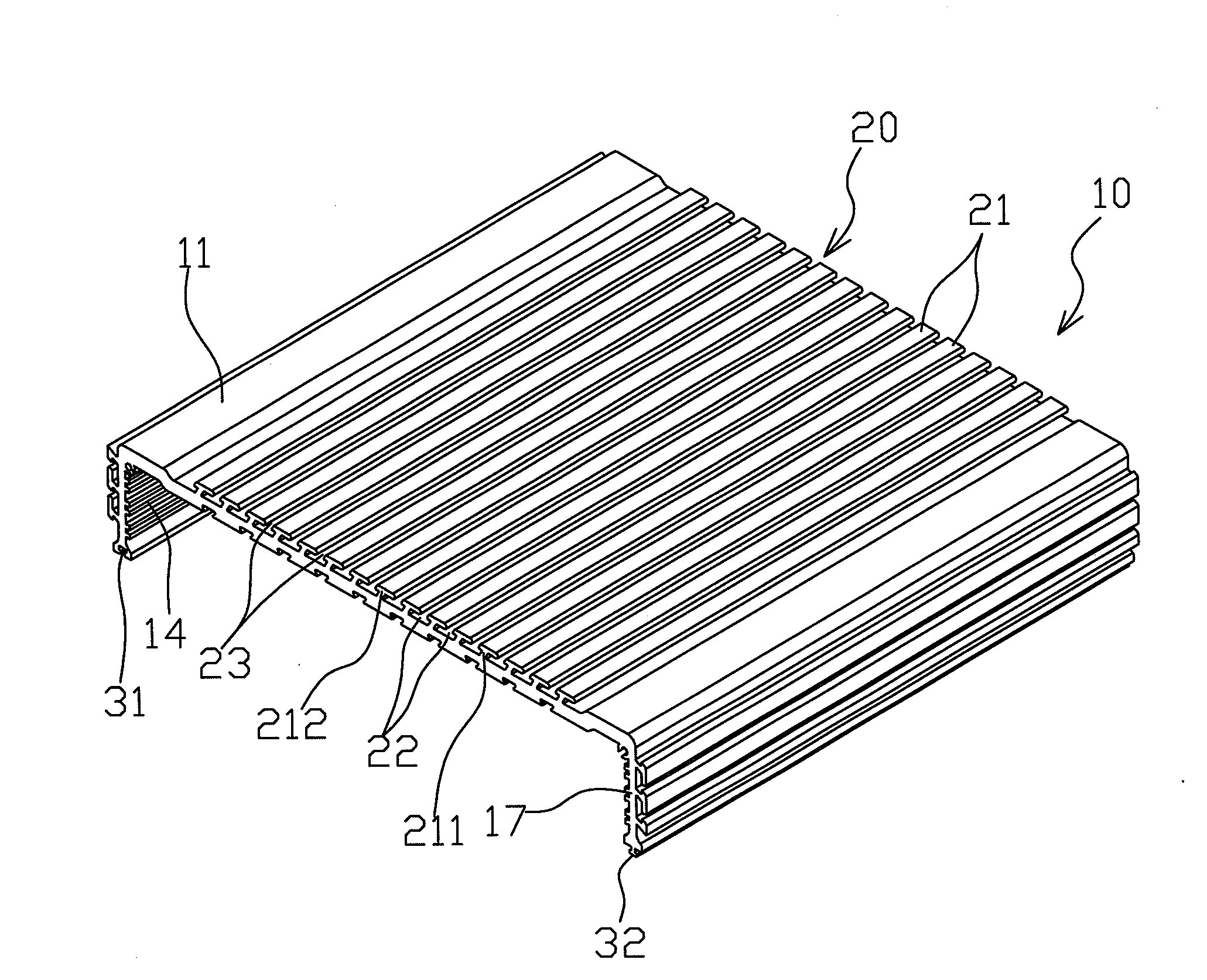
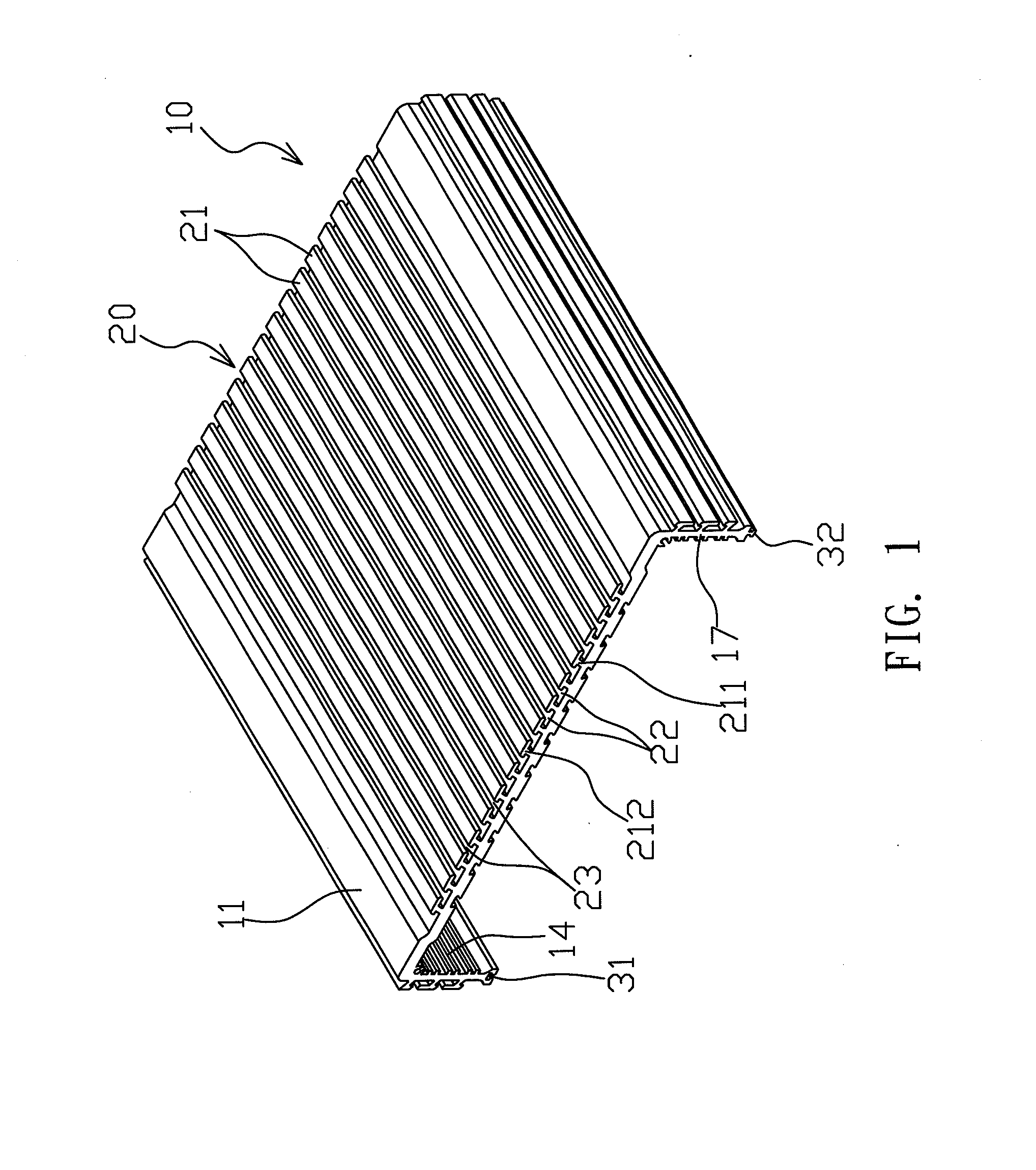
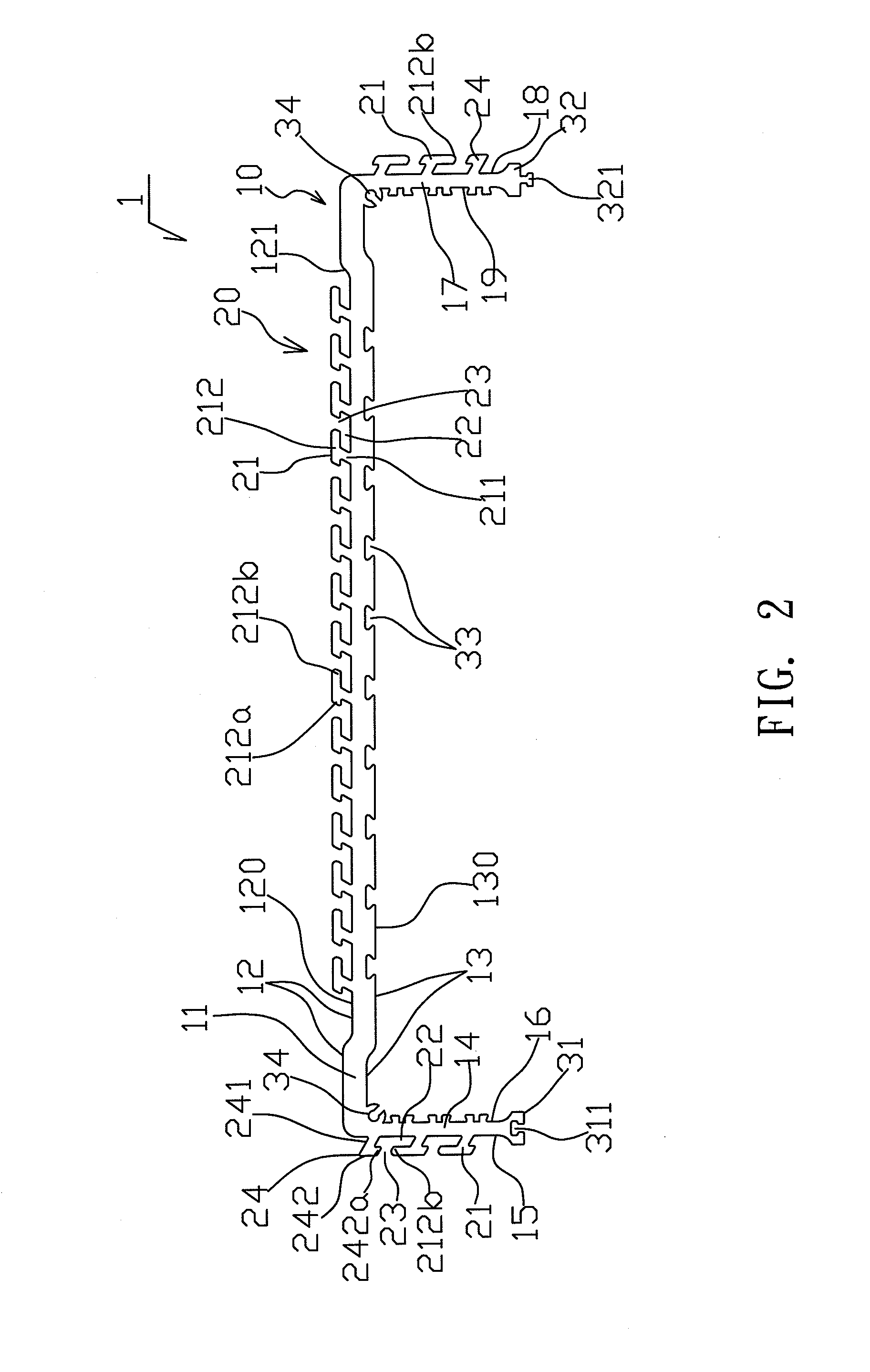
[0024]With reference to FIGS. 1 and 3, the combinational chassis 1 featuring heat dissipation according to this invention comprises a chassis body 10 and a heat dissipation device 20. The chassis body 10 comprises a base plane shell 11, and a first side shell 14 and a second side shell 17, of which the two sides are connected to each other in the same direction of the base plane shell 11. The base plane shell 11 is formed with an outside surface 12 and an inside surface 13. The internal surface 13 is further formed with a dovetail-shaped wedge slot 33, implemented in this embodiment but may also be implemented in another shape b...


PUM


Abstract

A combinational chassis featuring heat dissipation comprises a chassis body, a base plane shell, and a first side shell and a second side shell, of which the two sides connect to each other in the same direction of the base plane shell. A heat dissipation device comprises a plurality of heat-sink parts on the outside surface of chassis body. The heat-sink part comprises a raised portion integrally connected to the inside, and a joint portion connected to the outside. The raised portion integrally protrudes outwards from the outside surface. The joint portion geometrically protrudes from the raised portion. A wedge groove is formed near the joint portions where an inlet groove is formed. The inlet groove connects and communicates with the wedge groove. The chassis may be connected vertically in stack and / or connected horizontally for expansion to expand the computer system for preferably flexible application and optimal heat dissipation.

Description

BACKGROUND OF THE INVENTION[0001]1. Field of the Invention[0002]This invention relates to a combinational chassis featuring heat dissipation, which is designed for perfect combination space allocation, easy heat dissipation, and enhancement of the combined space utilization.[0003]2. Description of the Related Art[0004]Existing electronic equipment often have high-performance components or devices to work with and thus features heat dissipation; for example, important components installed in a computer, such as central processing unit (CPU), north and south bridge chips, hard drives and the like will produce heat when operating, and if the temperature of the component is too high, it will affect the performance of computer and will cause the computer to shutdown or impair the computer's service life. Accordingly, cooling measures are very important. The heat produced by the computer device is dissipated normally by a fan. However, some particular computer systems are not provided wit...

Claims


Application Information

Patent Timeline
IPC IPC(8): H05K7/20H05K5/02
CPCF28F3/048F28F9/001F28F2215/10F28F2275/14G06F1/181G06F1/20H05K5/0021H05K7/20409
Inventor CHANG, LERNG-HORNG
Owner TRUSTED SOLUTIONS CORP
Why Eureka
Try Eureka