
Rotor for oil pump

a technology for oil pumps and rotors, which is applied in the direction of liquid fuel engines, machines/engines, rotary piston liquid engines, etc., can solve problems such as loud noise, and achieve the effects of reducing backlash clearance, reducing noise of the rotors of the oil pump, and reducing backlash clearan

Active Publication Date: 2013-12-05
YAMADA SEISAKUSHO KK
View PDF4 Cites 0 Cited by
  • Summary
  • Abstract
  • Description
  • Claims
  • Application Information

AI Technical Summary

Benefits of technology

The present invention relates to improving the performance of oil pumps by reducing noise and rattling sounds caused by the rotation of rotors. The technical effects of this invention include preventing rattling sounds on the drive side, reducing noise caused by backlash, and achieving smooth contact between the teeth of the inner and outer rotors. These effects are achieved through the design of the intermediate region of the drive-side half-tooth region having a gentle slope and the non-drive-side half-tooth region having a steep slope, as well as configuring the outline of the drive-side half-tooth region with a smooth curve and the tooth of the inner rotor having an excellent curve.

Problems solved by technology

The problem in Patent Document 1, therefore, is this resultant loud noise.

Method used


Image

  • Rotor for oil pump
  • Rotor for oil pump
  • Rotor for oil pump

Examples


Embodiment Construction

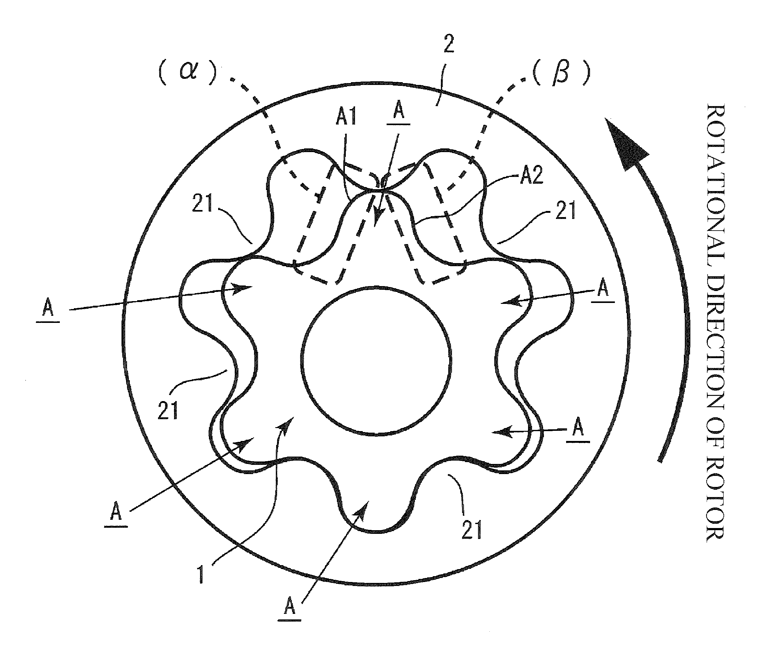
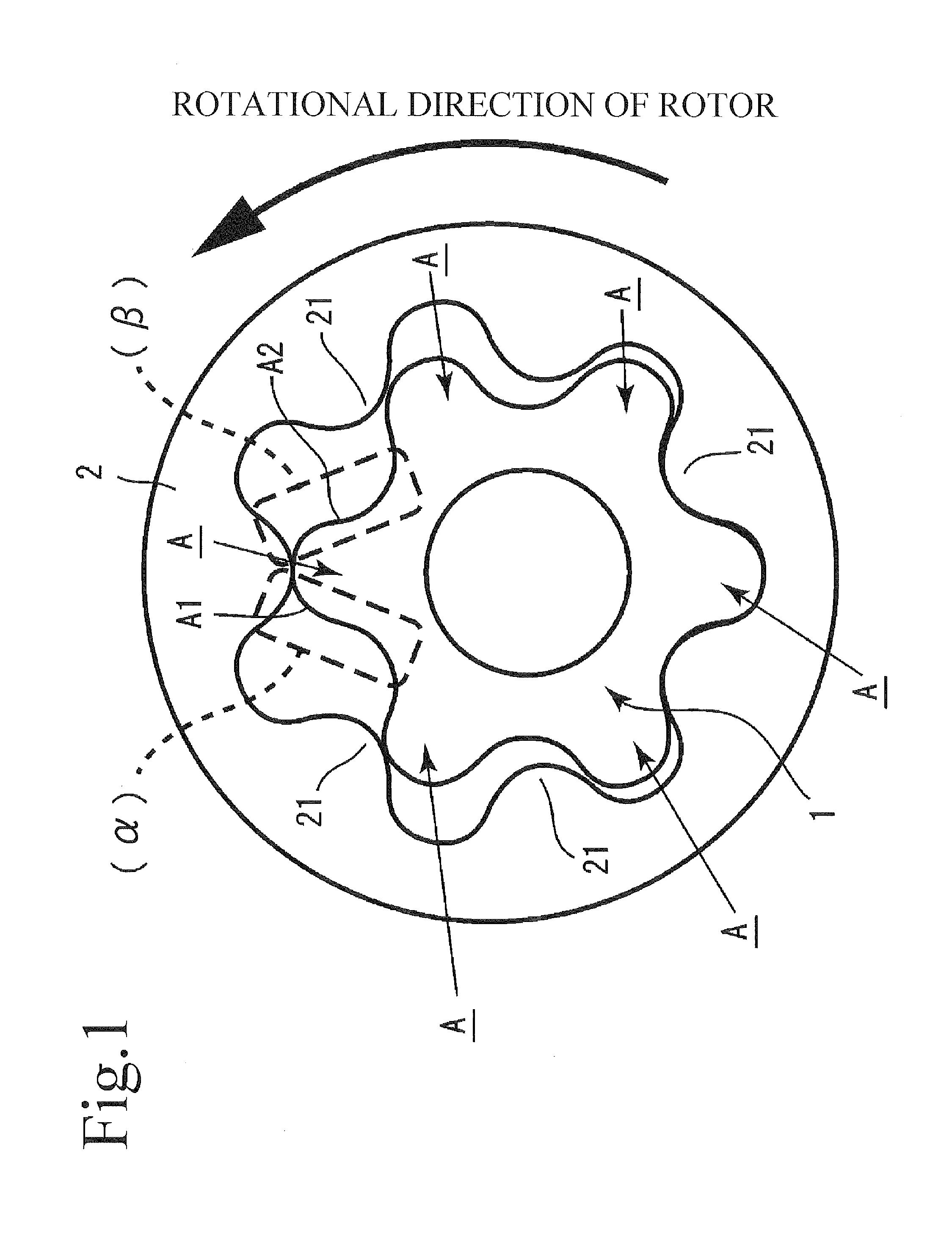
[0018]An embodiment of the present invention is described hereinafter with reference to the drawings. A pump rotor of the present invention is a gear-type rotor configuring an internal gear pump. This type of rotor generally has a combination of an inner rotor 1 and an outer rotor 2 that is disposed on the outside of the inner rotor 1 and rotates. The toothed inner rotor 1 with external teeth A is disposed on the inside of the annular outer rotor 2 having internal teeth. The outer rotor 2 rotates as the inner rotor 1 rotates.

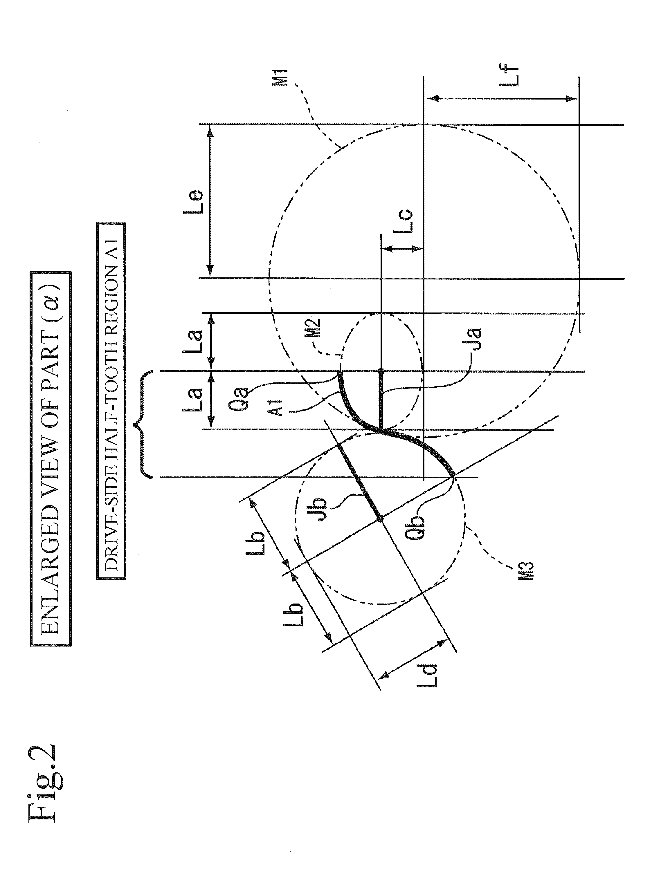
[0019]The inner rotor 1 is mainly described with regard to the pump rotor of the present invention. The inner rotor 1 here has six teeth; however, the number of teeth of the inner rotor 1 is not limited thereto and can be determined appropriately. First, the teeth A of the inner rotor 1 consist of a drive-side half-tooth region A1 and a non-drive-side half-tooth region A2.

[0020]One of the teeth A moves starting from the drive-side half-tooth region A1 to the non...


PUM


Abstract

A rotor for an oil pump according to the present invention is a rotor that includes an inner rotor configured by teeth, each of which has a plurality of ellipses or circles, and an outer rotor that is disposed on the outside of the inner rotor and has one tooth more than the inner rotor, wherein, in a tooth of the inner rotor, a tooth top and a tooth root of a drive-side half-tooth region extending from the tooth top to the tooth root and a tooth top and a tooth root of a non-drive-side half-tooth region extending from the tooth top to the tooth root are each configured by a different ellipse or a circle. A circumferential axis along a circumferential direction of the ellipse or circle configuring the tooth top is longer in the non-drive-side half-tooth region than in the drive-side half-tooth region.

Description

BACKGROUND OF THE INVENTION[0001]1. Field of the Invention[0002]The present invention relates to a rotor for an oil pump that is capable of reducing noise.[0003]2. Description of the Related Art[0004]Many of the conventional oil pumps are internal gear pumps that use trochoidal gears. For the purpose of improving the performances of these pumps, attempts have been made to change the shapes of details of the teeth of the outer rotor and the inner rotor in these pumps. Examples of the improved pumps include the one described in Japanese Patent Application Publication No. 2011-17318 (“Patent Document 1,” hereinafter).[0005]In Patent Document 1, one of the teeth of the inner rotor is constructed with a part of a curve extending along the circumferential axis of the ellipse of the tooth. As shown in FIGS. 6, 7, 8 and the like of Patent Document 1, the angle of each tooth curve of the inner rotor changes suddenly at the inflection point at which the ellipses are connected to each other. R...

Claims


Application Information

Patent Timeline
Patent Type & Authority Applications(United States)
IPC IPC(8): F04C2/10
CPCF04C2/10F04C2/084F04C2/102
Inventor FUJIKI, KENICHIIZUTSU, MASATOWATANABE, TAKATOSHI
Owner YAMADA SEISAKUSHO KK
Learn More