
Display device

a display device and display area technology, applied in the field of display devices, can solve the problems of alternate hot spots of bright and dark, and achieve the effect of a dark zone on the display area

Active Publication Date: 2013-12-05
CORETRONIC
View PDF3 Cites 21 Cited by
  • Summary
  • Abstract
  • Description
  • Claims
  • Application Information

AI Technical Summary

Benefits of technology

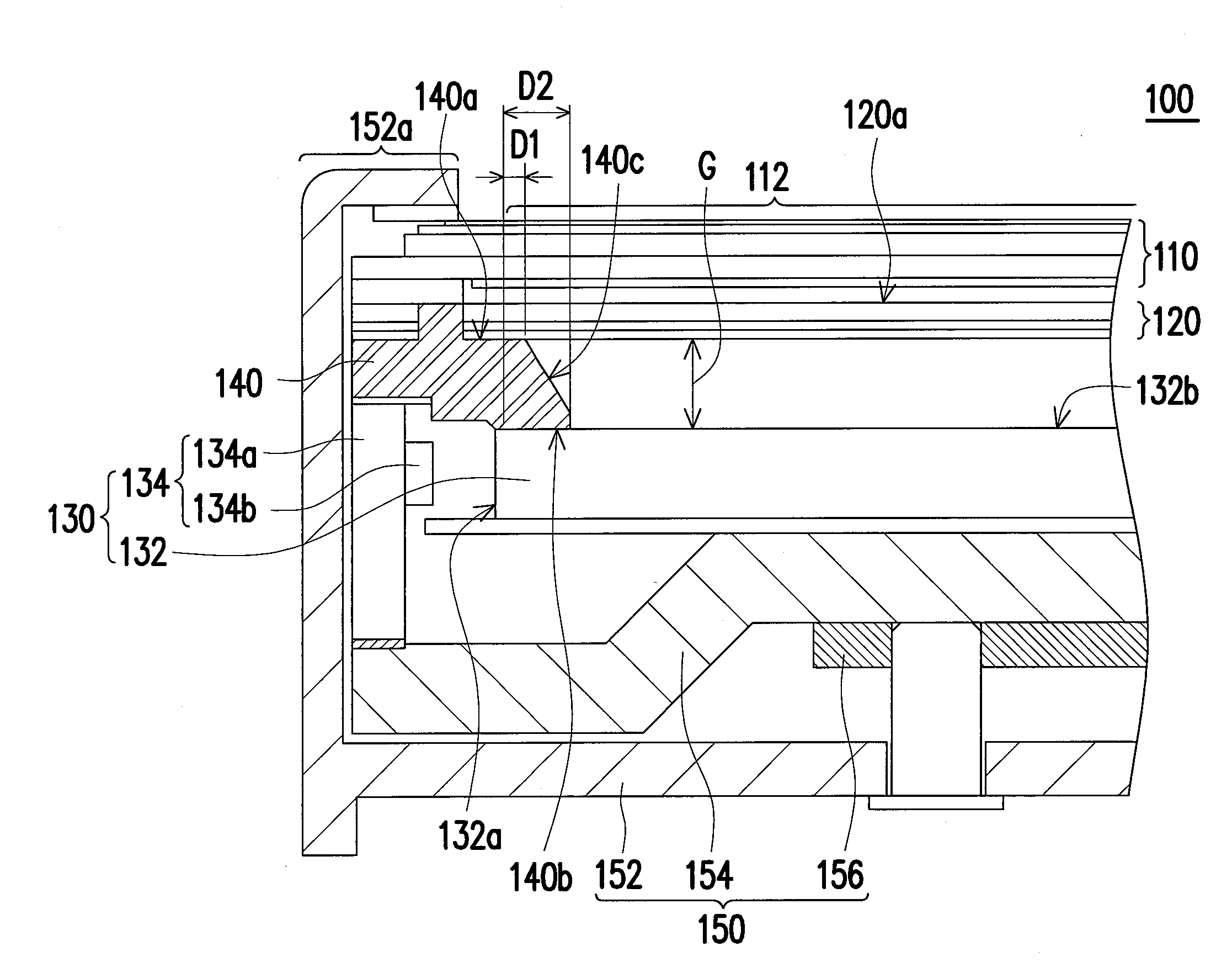
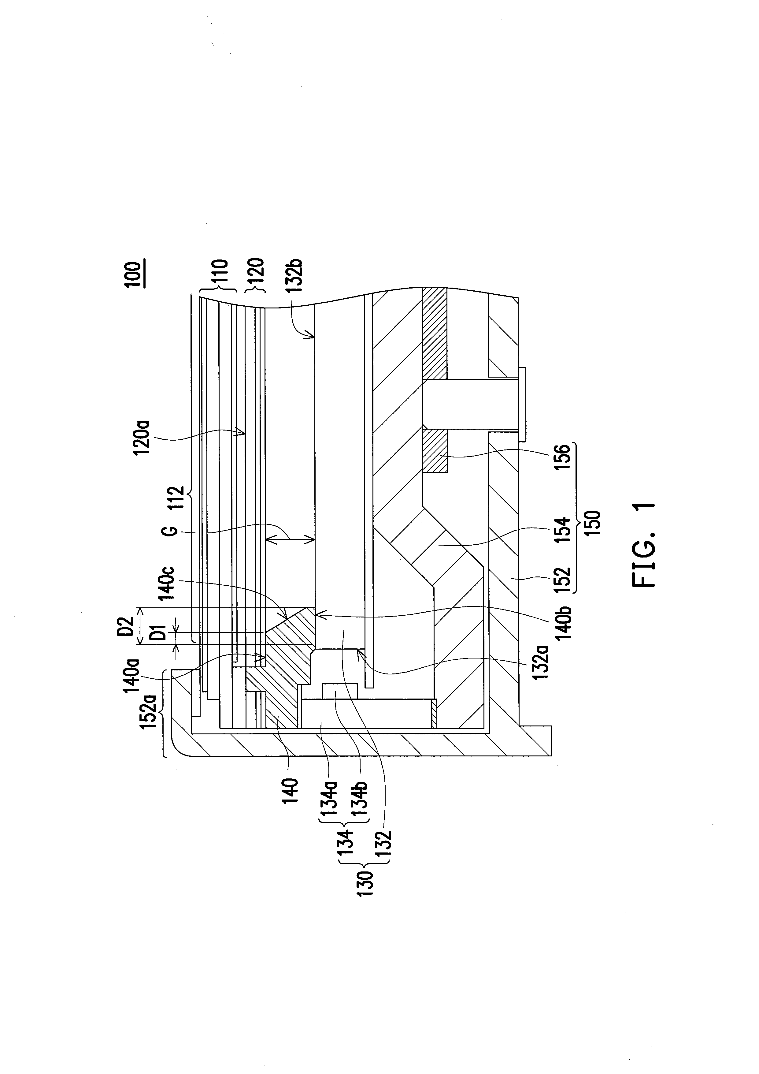
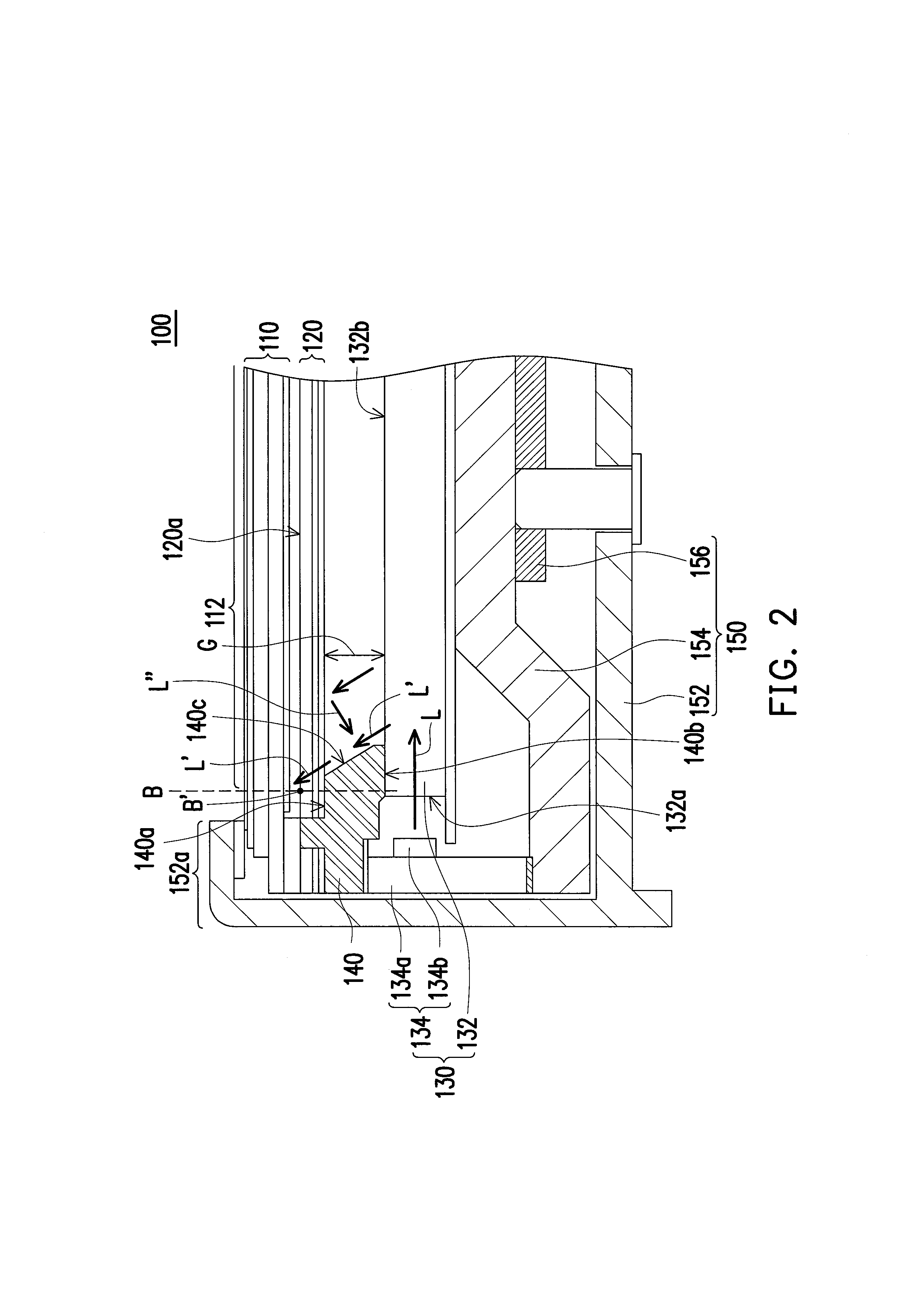
The invention is a display device that prevents the formation of dark areas on the display surface. This is achieved by using a frame that shields hot spots on the light guide plate and increases the distance between the light source and the display area. To prevent the frame from affecting the display area, a chamfered inclined surface is formed on the frame so that the distance between the frame and the light emitting surface of the light guide plate is smaller than the distance between the frame and the border portion of the display area. This results in a more even light emission and prevents the formation of dark areas, improving the quality of the display.

Problems solved by technology

Presently, the LCD is gradually developed to have a design of narrow bezel, and in order to cope with the design requirement of narrow bezel, a light mixing distance provided to the LED devices by the LGP is insufficient, which is easy to cause bright-dark alternated hot spots at a place on the LGP adjacent to the LED devices.
However, such design may cause a problem that the light incident to the active display area from the LGP is blocked by the frame, and a dark zone is generated at a border of the active display area.
In this way, the light emitting area of the light source module is not limited by the frame, and the border portion of the active display area is not easy to produce the dark zone, which improves display quality of the display device.

Method used


Image

  • Display device
  • Display device
  • Display device

Examples


Embodiment Construction

[0023]In the following detailed description of the preferred embodiments, reference is made to the accompanying drawings which form a part hereof, and in which are shown by way of illustration specific embodiments in which the invention may be practiced. In this regard, directional terminology, such as “top,”“bottom,”“front,”“back,” etc., is used with reference to the orientation of the Figure(s) being described. The components of the present invention can be positioned in a number of different orientations. As such, the directional terminology is used for purposes of illustration and is in no way limiting. On the other hand, the drawings are only schematic and the sizes of components may be exaggerated for clarity. It is to be understood that other embodiments may be utilized and structural changes may be made without departing from the scope of the present invention. Also, it is to be understood that the phraseology and terminology used herein are for the purpose of description an...


PUM


Abstract

A display device includes a display panel having an active display area, an optical film set, a light source module, and a frame. The light source module includes a light guide plate (LGP) and a light source adjacent to a side surface of the LGP. The optical film set is located between the display panel and the LGP. The frame disposed between the LGP and the optical film set extends to the LGP and covers a portion of the LGP. The frame has a first surface carrying the optical film set, a second surface facing to the light emitting surface, and a chamfered inclined surface. The chamfered inclined surface is within the active display area and connects the first and second surfaces. An extending distance of the first surface in the active display area is smaller than an extending distance of the second surface in the active display area.

Description

CROSS-REFERENCE TO RELATED APPLICATION[0001]This application claims the priority benefit of Taiwan application serial no. 101210246, filed on May 29, 2012. The entirety of the above-mentioned patent application is hereby incorporated by reference herein and made a part of this specification.BACKGROUND[0002]1. Technical Field[0003]The invention relates to a display device. Particularly, the invention relates to a display device having a light source module.[0004]2. Related Art[0005]Along with quick development of semiconductor industry and related electronics industry, digital devices such as mobile phones, digital cameras, digital video cameras, notebooks, desktop computers, and flat panel televisions, etc. are all developed to be more convenient, multifunctional, and aesthetic. When the above products are used, a display screen is an indispensable interface, and by using the display screen, the user's operation can be more convenient. In recent years, liquid crystal displays (LCDs)...

Claims


Application Information

Patent Timeline
IPC IPC(8): F21V8/00
CPCG02B6/0088G02B6/009G02F1/133317
Inventor YANG, WEN-PIN
Owner CORETRONIC
Learn More