
Device for Treating Water Comprising a Solid Filter Drum

a technology of solid filter drum and water treatment device, which is applied in the direction of water/sludge/sewage treatment, specific water treatment objectives, moving filter element filters, etc., can solve the problems of clogging and oxidation, premature wear of filters, and affecting etc., to achieve simple and economical implementation, increase the quality of sludg

Inactive Publication Date: 2013-11-28
VEOLIA WATER SOLUTIONS & TECH SUPPORT
View PDF5 Cites 6 Cited by
  • Summary
  • Abstract
  • Description
  • Claims
  • Application Information

AI Technical Summary

Benefits of technology

This patent aims to prevent the filter drum from getting damaged quickly when it gets rotating. It also tries to keep the sludges outside the chute and prevent the chute from getting overflowed during the unclogging of the filter drum.

Problems solved by technology

The filtered water collected at the bottom of this filtering zone can thus get mixed with the biologically treated but non-filtered water, and this would tend to diminish its quality.
These elements then tend, on the one hand, to get clogged and oxidized.
On the other hand, a premature wearing out is observed in these means for the rotational guiding of the filter drum.
The maintenance of such a plant represents a heavy cost item and leads to a drop in productivity.
In certain rare cases, in particular when the users do not carry out these maintenance campaigns regularly and stringently, the rollers may break, inducing damages that are more consequential, especially the stoppage of the plant.
Such stoppage can lead to non-treated wastewater being shed into the natural environment.
It can also give rise to a non-uniform growth of microorganisms on the surface of the biological disks, these microorganisms tending indeed to show higher growth on the immersed portion of the biological disks than on their emerged portion.
This leads to a phenomenon of imbalance when the plant is put back into operation.
Another drawback of this prior-art technique is related to the fact that the chute placed inside the filter drum to collect the sludges coming from the unclogging of the filter drum is mounted fixedly inside this drum.
It can thus happen that, after the plant has been assembled, the chute is not perfectly facing the injection bar placed outside the filter drum.

Method used


Image

  • Device for Treating Water Comprising a Solid Filter Drum
  • Device for Treating Water Comprising a Solid Filter Drum
  • Device for Treating Water Comprising a Solid Filter Drum

Examples


Embodiment Construction

[0057]7.1. Reminder of the principle of the invention

[0058]The general principle of the invention relies on the implementation of a filter drum, the sides of which are closed by solid sidewalls. One of its sidewalls is fixedly joined to a shaft placed upstream on which there are mounted biological disks. The other sidewall is crossed at its center by the piping for discharging sludges that come from the unclogging, and is guided on it in rotation.

[0059]Such an implementation prevents the splashing out of the filter drum of water treated only biologically and of sludges coming from the unclogging and therefore:[0060]prevents rapid deterioration of the means for guiding the filter drum in rotation;[0061]reduces the frequency of implementation of maintenance operations;[0062]increases productivity;[0063]improves the quality of the treated water produced.

[0064]7.2. Example of a device for treating water according to the invention

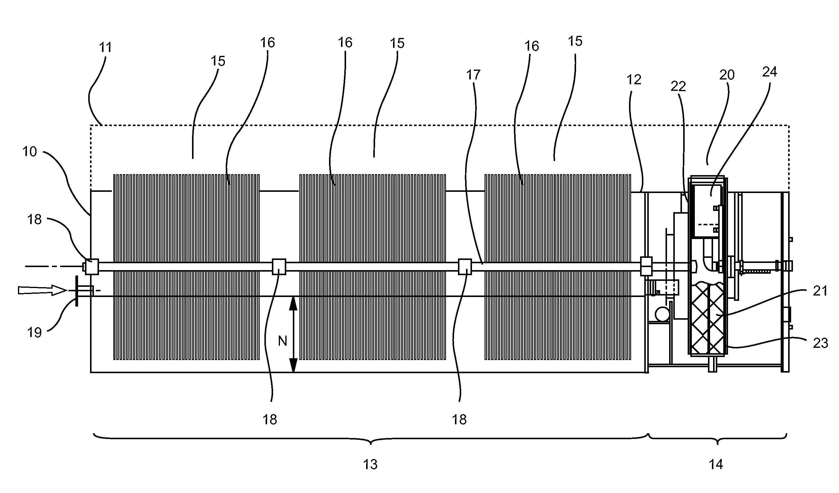
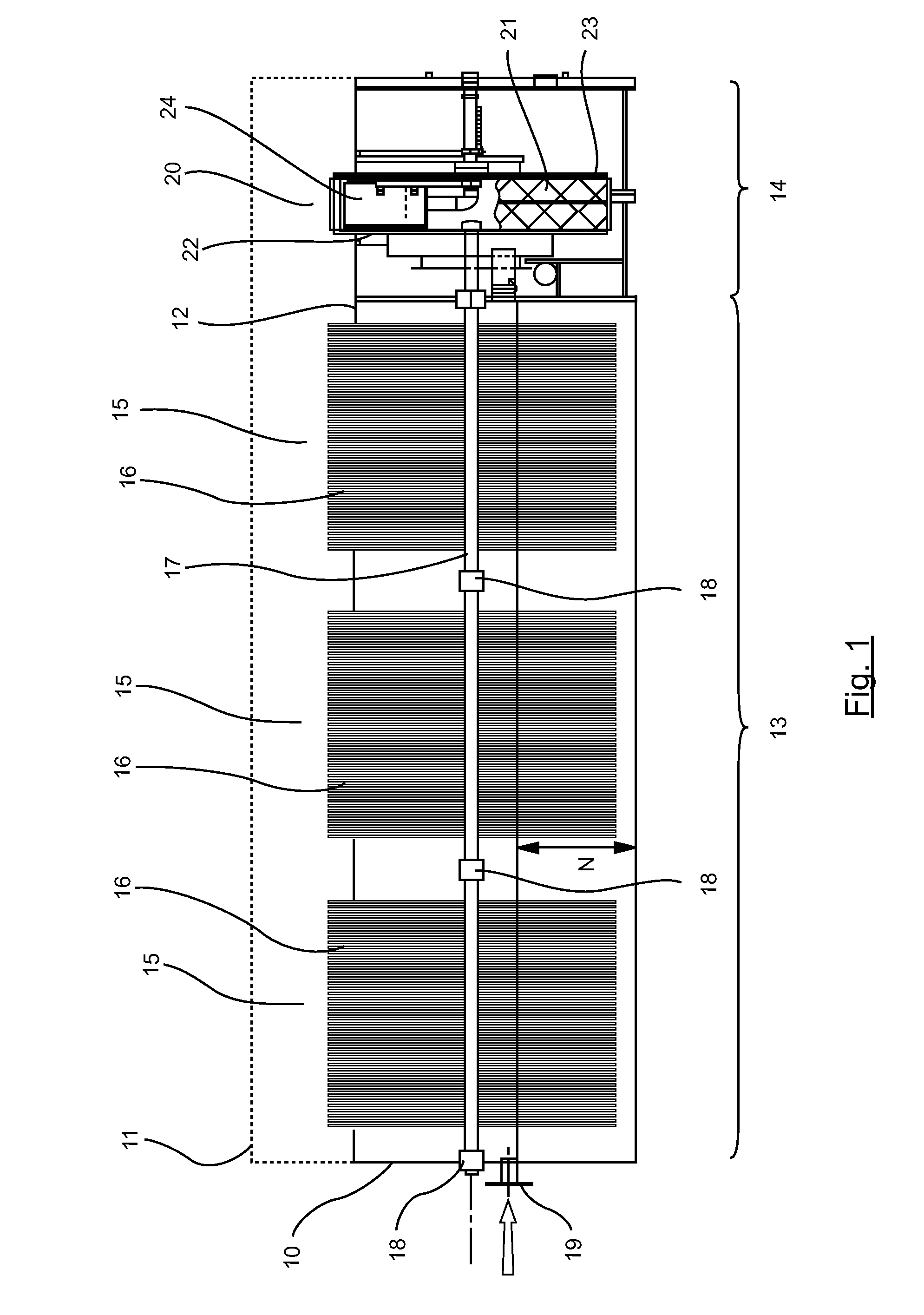
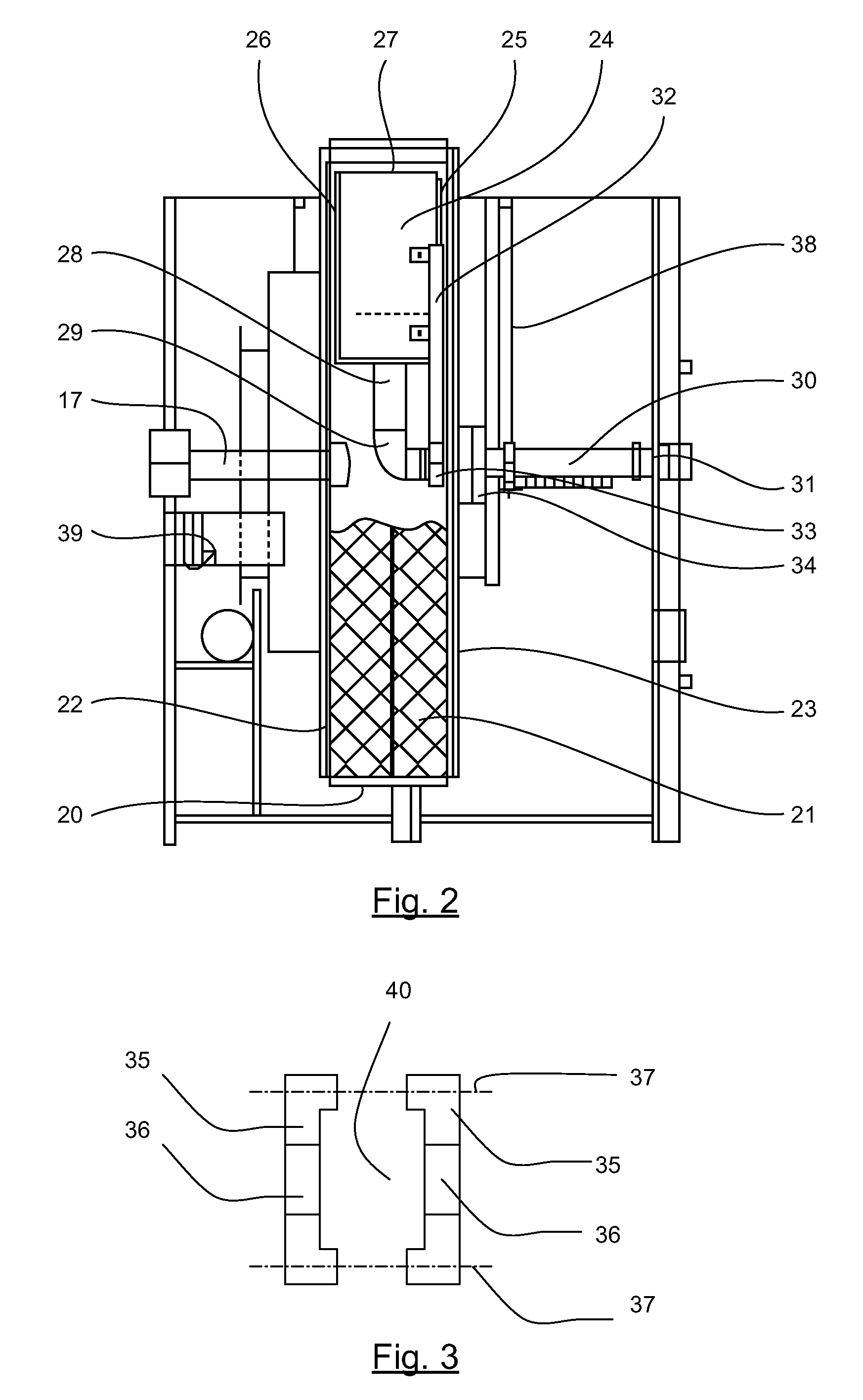
[0065]Referring to FIGS. 1 and 2, we present an embodiment...


PUM

PropertyMeasurementUnit
areaaaaaaaaaaa
gravityaaaaaaaaaa
frequencyaaaaaaaaaa

Abstract

Device for treating water comprising a solid filter drum. The invention relates to a device for treating water comprising:—a biological treatment zone (13) housing a plurality of biological discs (16) mounted on a shaft (17) that can be turned, —a filtration zone (14) housing a filter drum (20) mounted on the same shaft as the said biological discs (16), —conveying means (39) for conveying biologically treated water originating from said biological treatment zone (13) into said filter drum (20), —means for unplugging said filter drum (20), which means are positioned on the outside of said filter drum (20), —sludge collection means (24) positioned inside said filter drum (20) facing said unplugging means and connected to a discharge line (28, 29, 30) that discharges said sludge from said filter drum (20). According to the invention, the sides of said filter drum (20) are closed by solid sidewalls (22, 23), and said discharge line (28, 29, 30) comprises a portion (30) which extends along the axis of said shaft (17) through a first of said sidewalls (23) mounted to rotate about said axis, the second sidewall (22) of said filter drum (20) being secured to said shaft (17).

Description

1. FIELD OF THE INVENTION[0001]The field of the invention is that of plants implemented to carry out the biological treatment of wastewater.[0002]More specifically, the invention pertains to a plant for treating water comprising a biological treatment zone housing biological disks followed by a filtering zone housing a filter drum.2. PRIOR ART[0003]The French patent application number FR-A1-2 916 436 filed by the present Applicant, describes such a plant.[0004]More specifically, such a plant comprises a biological treatment zone housing a plurality of biological disks mounted on a shaft capable of being driven in rotation.[0005]A raw water is conveyed into this zone so as to be treated biologically in contact with the biological disks.[0006]This biological treatment zone is followed by a filtering zone housing a filter drum mounted in the same axis as said biological disks. A piping enables the conveyance by gravity of a biologically treated water coming from the biological treatmen...

Claims


Application Information

Patent Timeline
Patent Type & Authority Applications(United States)
IPC IPC(8): C02F3/00
CPCC02F3/00B01D33/11C02F1/001C02F3/08C02F3/082C02F2201/003C02F2303/20B01J23/28Y02W10/10
Inventor SCHMITT, THOMASHERTFELDER, NIKOLAI
Owner VEOLIA WATER SOLUTIONS & TECH SUPPORT
Learn More