Non-latitude and vertically mounted solar energy concentrators
a solar energy concentrator, vertical mounting technology, applied in the direction of pv power plants, instruments, analogue processes for specific applications, etc., can solve the problems of low solar module efficiency, low material and manufacturing costs, and limited the scale of solar power development required to effectively, so as to achieve the maximum effect of benefi
- Summary
- Abstract
- Description
- Claims
- Application Information
AI Technical Summary
Benefits of technology
Problems solved by technology
Method used
Image
Examples
embodiment 550
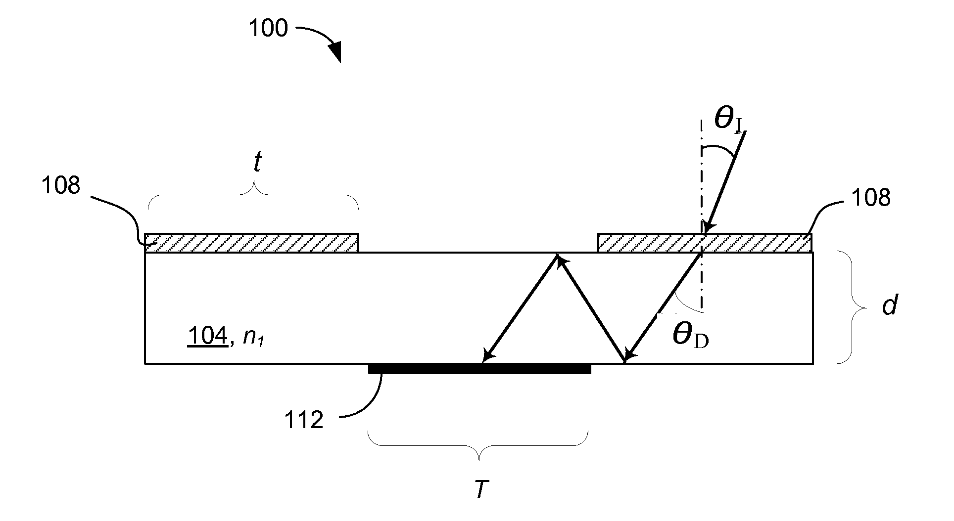
[0064]For simplicity of illustrations, the following discussion refers to PV modules of the invention that are substantially vertically mounted in the northern hemisphere. PV modules mounted to face the equator receive very little light—if at all—from the backside. Accordingly, the PV cell does not have to be a bifacial PV cell. An example of a PV-module 500 of the invention employing monofacial PV cell(s) 510 and an array of diffractive gratings 520. A diffraction grating pattern of each of the gratings in the array 520 (which, in the case of imprinted grating such as a blazed grating corresponds to the grating grooves or rulings, and in the case of a holographically-defined gratings corresponds to the iso-lines of refractive index distribution in a plane parallel to the plane of the grating) generally corresponds to the extent of a grating in the array, i.e. is substantially horizontal in the local system of coordinates, as shown in diagrams of FIGS. 5A, 5B. A beam of sunlight 530...
embodiment 900
[0068]A related embodiment 900 of the invention, as shown in FIG. 9 in a front view, includes PV cells 910 and a diffractive element layer containing diffraction gratings 920a, 920b oriented such that their corresponding Bragg planes form a dihedral angle A. Generally, the value of A can vary, from embodiment to embodiment, within a range between 0 and 180 degrees. As shown in FIG. 9, A˜90 degrees and the grating pattern 920a, 920b is oriented, in the plane of the module (xy-plane), at about B=45 degrees to the x-axis. Such configuration of the gratings 920a, 920b is adapted to optimize the solar-energy collection by a module that faces a direction between the east / west and north / south (for example, the south-east).
embodiment 1000
[0069]Another embodiment 1000, characterized by A˜90 degrees and B˜0 degrees, is shown in FIG. 10. Diffraction grating elements 1010 with vertically-oriented diffraction pattern optimize the performance of the module 1000 with respect to east-west orientation of the embodiment, while diffraction grating element 1020 with horizontally oriented pattern optimize the performance of the module 1000 with respect to north-south orientation. Accordingly, at least one of the (groups of) gratings 1010, 1020 receives sunlight and diffracts it towards the PV cells 1030 at any time during the day of any month of the year, regardless of at which angle with respect to the north-south / east-west coordinates the substantially-vertically positioned module 1000 is oriented.
[0070]It is worth mentioning that, in addition to optimizing the solar energy collection in any orientation with respect to the four cardinal directions (north, east, south, west), the vertically-mounted embodiments 900, 1000 of FIGS...
PUM
 Abstract
Description
Claims
Application Information
 - R&D
- Intellectual Property
- Life Sciences
- Materials
- Tech Scout
- Unparalleled Data Quality
- Higher Quality Content
- 60% Fewer Hallucinations
Browse by: Latest US Patents, China's latest patents, Technical Efficacy Thesaurus, Application Domain, Technology Topic, Popular Technical Reports.
© 2025 PatSnap. All rights reserved.Legal|Privacy policy|Modern Slavery Act Transparency Statement|Sitemap|About US| Contact US: help@patsnap.com


