
Mobile station and method for use in radio communication system

a mobile station and radio communication technology, applied in the field of radio communication system, can solve the problems that the electromagnetic waves transmitted from a mobile station may affect the human body

Active Publication Date: 2013-11-21
NTT DOCOMO INC
View PDF12 Cites 32 Cited by
  • Summary
  • Abstract
  • Description
  • Claims
  • Application Information

AI Technical Summary

Benefits of technology

The patent text describes a way to determine the maximum amount of power a mobile device can use when transmitting signals. This helps to ensure that the device operates efficiently and doesn't cause any interference with other devices.

Problems solved by technology

Meanwhile, it is known that electromagnetic waves transmitted from a mobile station may affect the human body.

Method used


Image

  • Mobile station and method for use in radio communication system
  • Mobile station and method for use in radio communication system
  • Mobile station and method for use in radio communication system

Examples


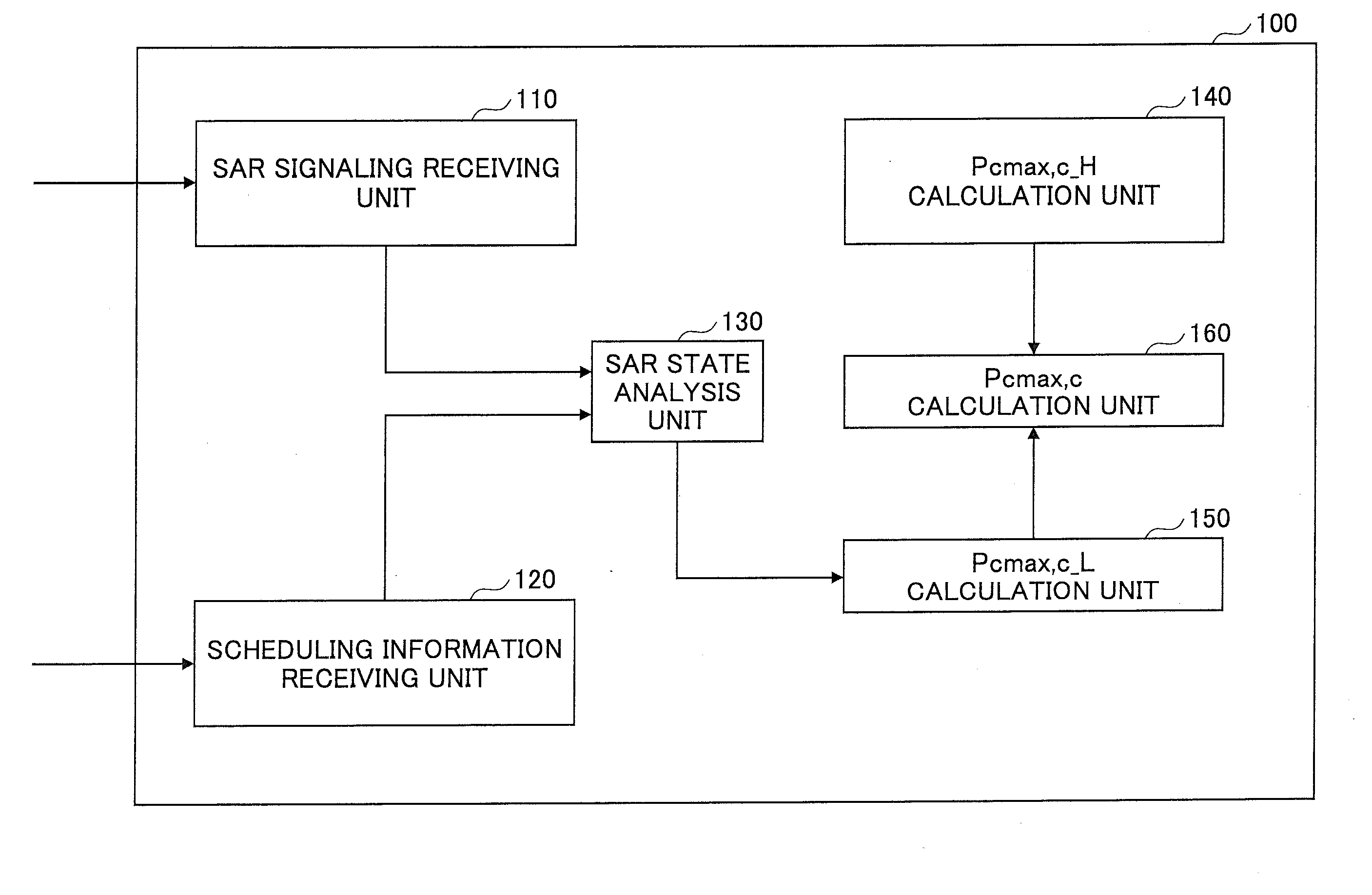
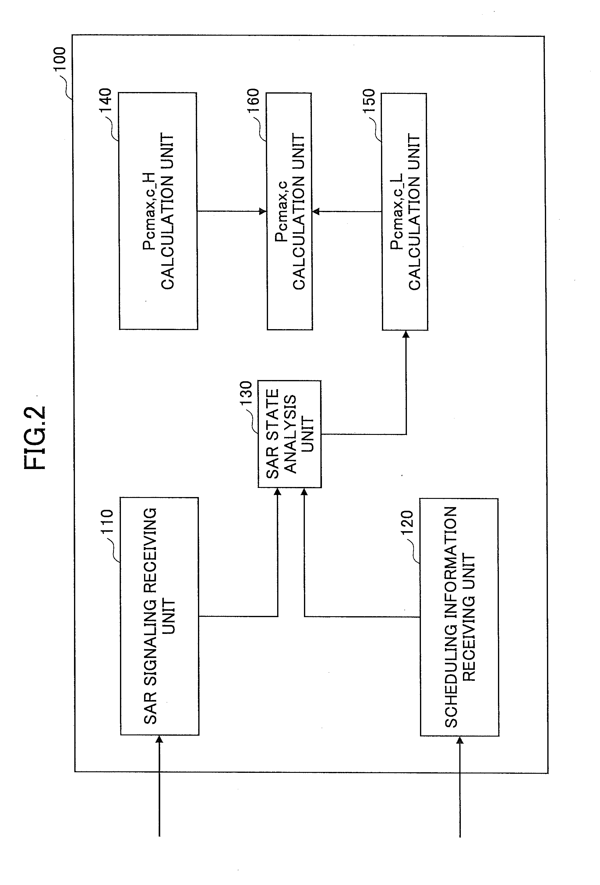
first embodiment

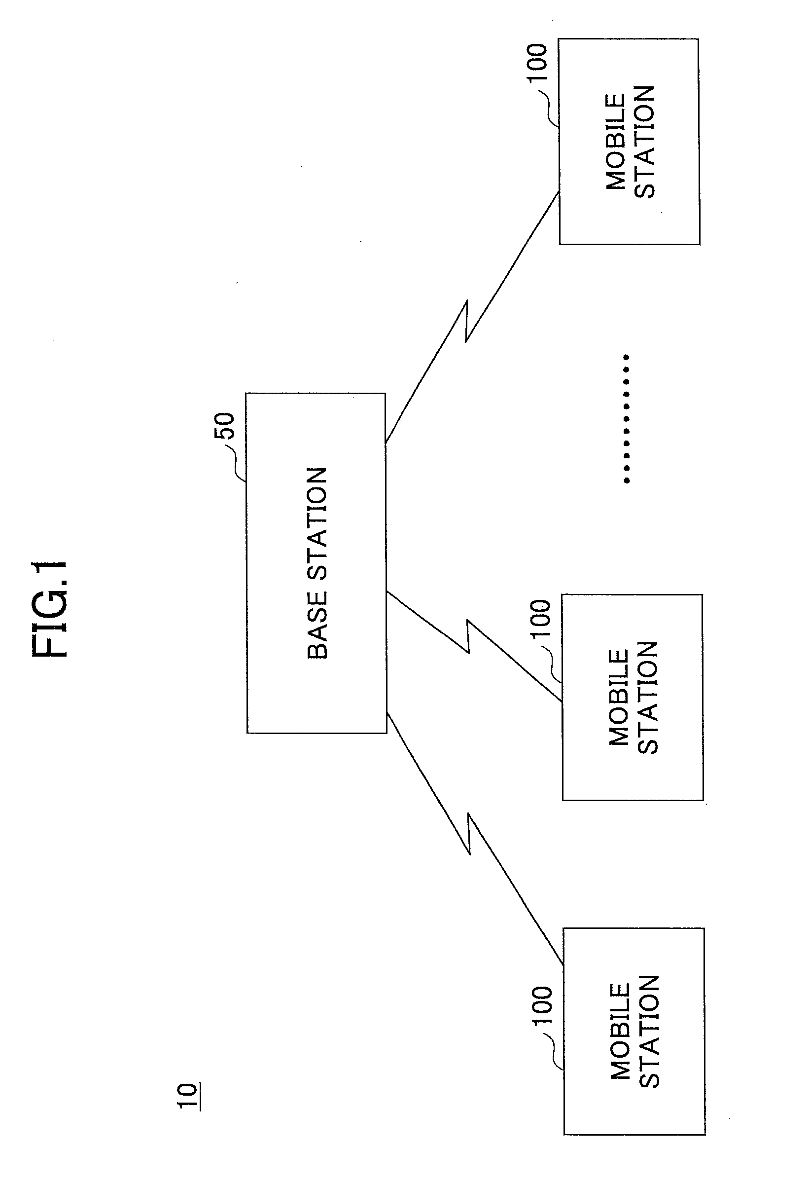
[0029]A mobile station according to the present invention is described with reference to FIGS. 2-4. In this embodiment, the base station 50 sends the mobile station 100 a SAR signaling to allow the mobile station 100 to use the SAR backoff, and when receiving the SAR signaling, the mobile station 100 applies the SAR backoff to determine the maximum transmit power Pcmax, c for each CC.

[0030]FIG. 2 is a block diagram for illustrating the mobile station according to the first embodiment of the present invention. As illustrated in FIG. 2, the mobile station 100 includes a SAR signaling receiving unit 110, a scheduling information receiving unit 120, a SAR state analysis unit 130, a Pcmax, c—H calculation unit 140, a Pcmax, c—L calculation unit 150 and a Pcmax, c calculation unit 160.

[0031]The SAR signaling receiving unit 110 receives a SAR signaling from the base station 50 for allowing the mobile station 100 to use the SAR backoff. In one embodiment, the base station 50 broadcasts the ...

second embodiment

[0051]Next, a mobile station according to the present invention is described with reference to FIGS. 5-6. In this embodiment, a mobile station uses a country code included in broadcast information from a base station to determine whether the SAR backoff can be applied in the radio communication system and derives the maximum transmit power Pcmax, c for each CC depending on the determination result.

[0052]FIG. 5 is a block diagram for illustrating a mobile station according to the second embodiment of the present invention. As illustrated in FIG. 5, a mobile station 200 includes a country code receiving unit 210, a scheduling information receiving unit 220, a SAR state analysis unit 230, a Pcmax, c—H calculation unit 240, a Pcmax, c—L calculation unit 250 and a Pcmax, c calculation unit 260. Here, the Pcmax, c—H calculation unit 240, the Pcmax, c—L calculation unit 250 and the Pcmax, c calculation unit 260 perform the same operations as the Pcmax, c—H calculation unit 140, the Pcmax, ...


PUM


Abstract

One aspect of the present invention relates to a mobile station having a SAR backoff function including a SAR signaling receiving unit configured to receive a SAR signaling from a base station, the SAR signaling indicating that a SAR backoff is available, and a maximum transmit power determination unit configured to determine maximum transmit power of the mobile station depending on whether the SAR signaling receiving unit has received the SAR signaling, wherein in response to receiving the SAR signaling at the SAR signaling receiving unit, the maximum transmit power determination unit applies a power reduction factor associated with the SAR backoff to determine the maximum transmit power.

Description

TECHNICAL FIELD[0001]The present invention generally relates to a radio communication system and more particularly relates to techniques for determining transmit power of a SAR backoff enabled mobile station.BACKGROUND ART[0002]In a LTE (Long Term Evolution) scheme, an OFDMA (Orthogonal Frequency Division Multiple Access) scheme is used as a downlink radio access scheme, and a SC-FDMA (Single-Carrier Frequency Division Multiple Access) scheme is used as an uplink radio access scheme.[0003]The OFDMA scheme is a multi-carrier transmission scheme where a frequency band is segmented into multiple narrower frequency bands (subcarriers) and data is transmitted in the individual subcarriers. According to the OFDMA scheme, faster transmission and improved frequency utilization efficiency can be achieved by densely arranging the subcarriers orthogonally to a frequency axis.[0004]The SC-FDMA scheme is a single-carrier transmission scheme where a frequency band is segmented and different frequ...

Claims


Application Information

Patent Timeline
Patent Type & Authority Applications(United States)
IPC IPC(8): H04W52/18
CPCH04W52/367H04W52/18Y02B60/50H04W36/24H04W36/0072H04W52/365H04W52/34H04B1/3838
Inventor SAGAE, YUTANISHIKAWA, DAISUKEISHII, HIROYUKI
Owner NTT DOCOMO INC
Learn More