Method of measuring loadings in joins in a high-temperature environment and instrumented shaft for implementation, in particular for rear attachment of aircraft turbojet

Active Publication Date: 2013-11-21
AIRBUS OPERATIONS SAS
View PDF3 Cites 11 Cited by
  • Summary
  • Abstract
  • Description
  • Claims
  • Application Information

AI Technical Summary

Benefits of technology

The invention proposes to create instrumentation that can measure the loads passing through mechanical joints, such as engine rear attachments, without affecting their ability to transfer loads safely. The instrumented component is designed to encourage the measurement of bending. This will help to better evaluate the dimensions and mass of the load-bearing regions.

Problems solved by technology

Now, these loadings are currently estimated using calculation and are extensively overestimated because of uncertainty regarding the values obtained.
However, in the intended type of application, flexible strain gauges bonded to metal bars cannot be used.
However, this need is incompatible with the requirement for the shaft to have sufficient fatigue strength.
In addition, current instrumentation using these gauges does not allow them to be used beyond temperatures of the order of 280° C., because such instrumentation is unable to withstand high temperatures, for example 450° C. Thus, in the region of the rear engine attachment, where high temperatures are reached because of the proximity to the casing via which the residual hot gases are ejected and the proximity to the combustion casing, any conventional instrumentation is destroyed in the few minutes following the starting of the engine, because of the heat produced.
However, these gauges are no more suitable because of their size.
In particular, the significant curvature of the hollow shafts and the small dimensions inside the shaft mean that these shafts cannot be instrumented.

Method used


Image

  • Method of measuring loadings in joins in a high-temperature environment and instrumented shaft for implementation, in particular for rear attachment of aircraft turbojet
  • Method of measuring loadings in joins in a high-temperature environment and instrumented shaft for implementation, in particular for rear attachment of aircraft turbojet
  • Method of measuring loadings in joins in a high-temperature environment and instrumented shaft for implementation, in particular for rear attachment of aircraft turbojet

Examples


Embodiment Construction

[0021]As illustrated by the lateral view of FIG. 1, a turbojet engine 100 (herein after referred to as “engine”) of the type having a fan is made up of an air intake 101 coupled to a large-diameter upstream casing 110 housing the fan, this casing being followed by a downstream power-generator casing 120, hereinafter referred to as “engine casing”, which combines several casings—of substantially smaller diameters—housing the compression, combustion, expansion stages in the turbines and the ejection stages in the nozzles, and generally exhibiting symmetry of revolution about an axis X′X.

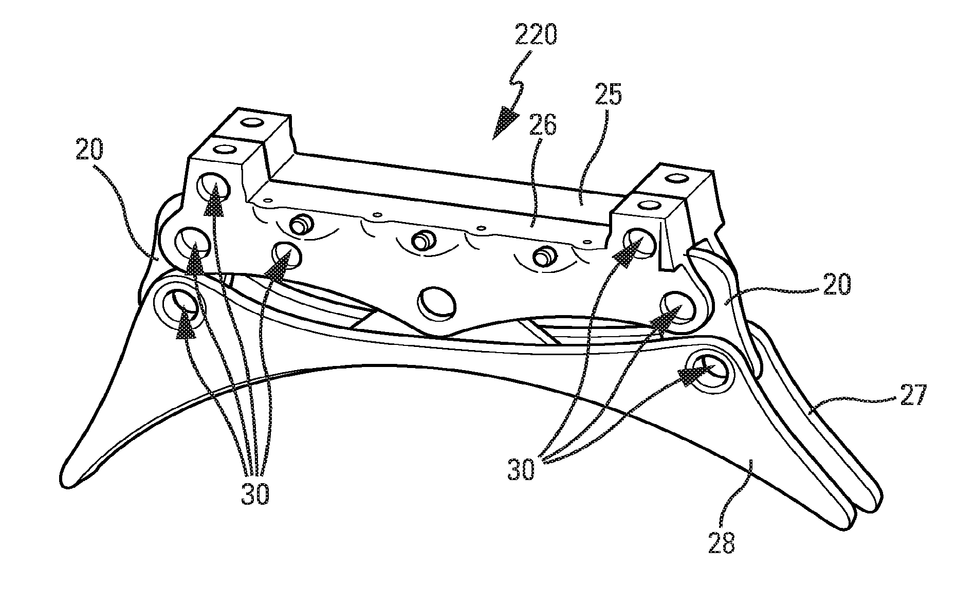
[0022]Suspending the engine 100 under a wing allows the load of the engine to be transferred to the wing structure of the aircraft via a suitable intermediate support structure. Conventionally, this support is a rigid pylon 200 of elongate shape, to which the engine 100 is attached using intermediate attachments extending in a plane substantially perpendicular to the structural casings and to the pylon...


PUM


Abstract

The invention aims to produce an instrumentation making it possible to measure the loadings which pass through mechanical joins between two mechanical structures, so as to best evaluate the dimensions and masses without impairing their mechanical properties of a secure transfer of load. To this end, the invention proposes introducing into the zones of transit of the loadings an instrumented component of the form that favours the measurement of shear and its installation. In one embodiment, a zone of transit of loadings consists of an instrumentalized hollow shaft which takes the form of a cylinder (1) able to be introduced into collinear openings (30) in the fittings (20, 25, 26). It comprises a longitudinal housing (10) into which is introduced an insert (2) composed of a central prop (21) in tight contact with the internal wall (1i) of the shaft (1) and connected, on each side, to a flyweight (31, 32) also in tight contact, by way of multiple tabs (41 to 44) away from contact with said internal wall (1i). High-temperature gauges (51, 53, 55, 57) are welded to the tabs (41 to 44), so as to measure a variation in electrical resistance corresponding to the bending deformation of the tabs (41 to 44).

Description

TECHNICAL FIELD[0001]The invention relates to a method for measuring loadings through joins between mechanical structures located in a high-temperature environment and to an instrumented shaft for implementing this measurement. The invention applies in particular, although not exclusively, to the rear suspension attachments of aircraft turbojet engines.[0002]Awareness of the intensity and the direction of shear loadings, passing through a join between mechanical structures that are working under load, allows the size of the joining components and the frequency with which these components are inspected to be optimized. In general, the loadings pass through the join in specific regions through which they pass, for example hollow pin or “hollow shaft” connections between the joining pieces. It is therefore in these regions that the loadings are measured.PRIOR ART[0003]A sufficiently precise and dependable measurement of the loadings means that lean design principles can be applied to t...

Claims


Application Information

Patent Timeline
IPC IPC(8): G01M17/04
CPCG01M17/04B64D2045/0085G01L1/2225G01L5/0004G01L5/1627B64D27/40G01L1/22G01L1/2218
Inventor MAGNIN, HERVEHACHE, GERALDINE
Owner AIRBUS OPERATIONS SAS
Why Eureka
Try Eureka