
Control room for nuclear power plant

a control room and nuclear power plant technology, applied in the direction of instruments, nuclear elements, greenhouse gas reduction, etc., can solve the problems of complex control room, unwieldy layout, high complexity of nuclear power plants

Active Publication Date: 2013-11-07
BWXT MPOWER INC
View PDF6 Cites 31 Cited by
  • Summary
  • Abstract
  • Description
  • Claims
  • Application Information

AI Technical Summary

Benefits of technology

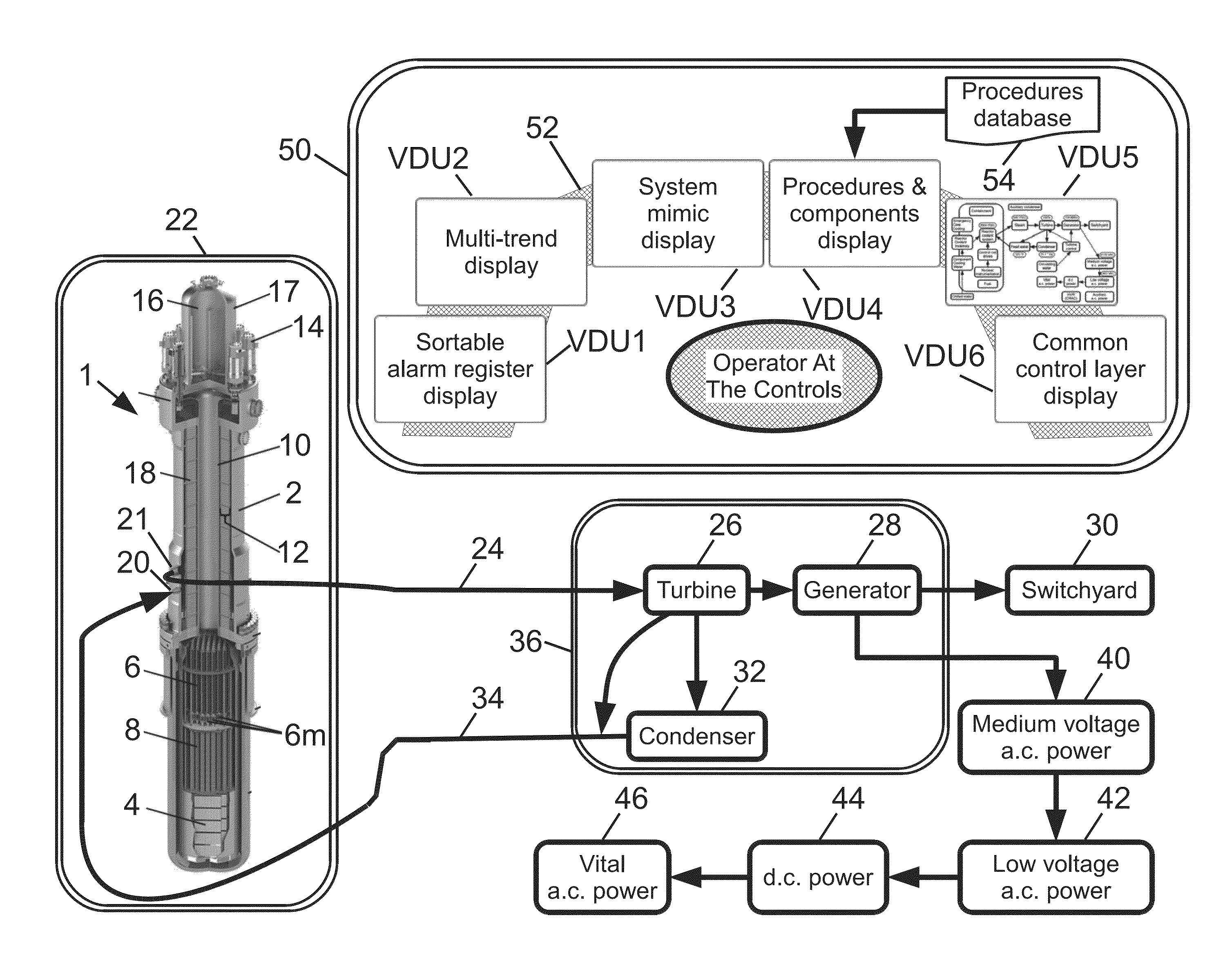
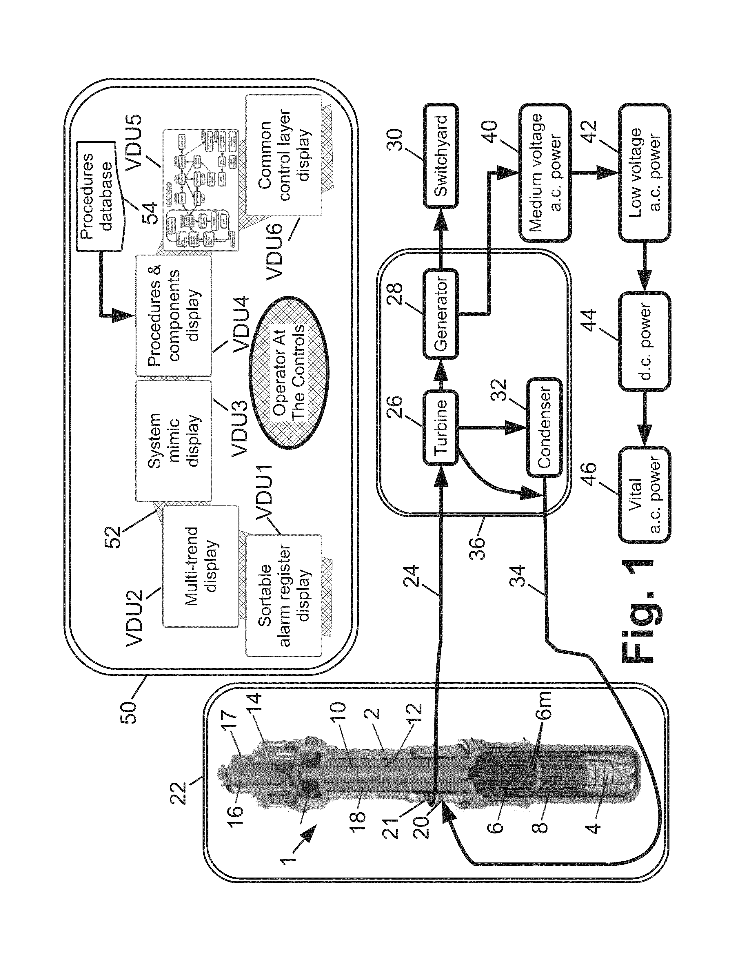
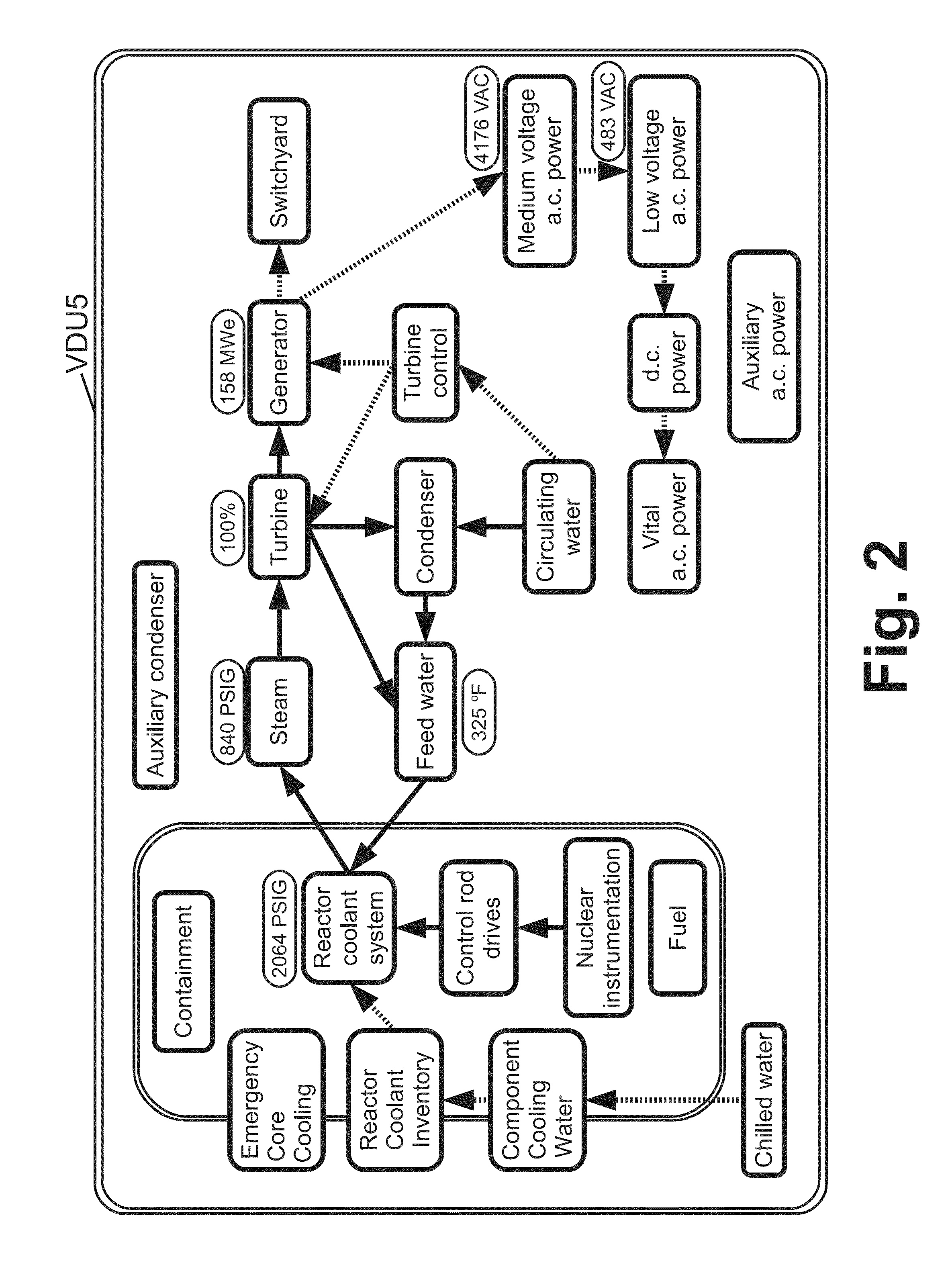
This patent describes a method for displaying a home screen on a video display unit at a nuclear power plant. The home screen includes blocks that represent different functional components of the nuclear power plant. Connecting arrows on the screen represent the direction of heat flow along different paths. When the plant transitions to a new heat sinking path, the method updates the connecting arrows to reflect the new path. The technical effect of this invention is that it provides a visual representation of the heat sinking path of a nuclear power plant, which can help to improve safety and efficiency.

Problems solved by technology

Nuclear power plants are highly complex and include numerous systems to ensure safe operation.
The resulting layout is unwieldy, including numerous control panels with typically dozens of video display units (VDUs) along with additional indicator lights, and various operator controls such as touch-screen VDU interfaces along with switches, buttons, and so forth.
Nonetheless, the control room is complex.
When an abnormal situation arises, it typically results in numerous alarms being set off at various control panels associated with the various components affected by the abnormal situation.
For example, a failure of the condenser will cause automated shutdown of the turbine, interrupts the steam flow, trips the reactor and brings the ECCS online; and, as further consequences reactor pressure and temperature likely will rise and various electrical systems may also react.
Any error in diagnosing the root cause may result in incorrect remedial action which can delay resolution of the root cause and may possibly introduce further problems.

Method used


Image

  • Control room for nuclear power plant
  • Control room for nuclear power plant
  • Control room for nuclear power plant

Examples


Embodiment Construction

[0019]Disclosed herein are improved control room designs that substantially enhance the effectiveness of the nuclear power plant operators.

[0020]In existing control rooms for nuclear power plants, a large number of VDUs (e.g. 30, 40, or even more VDUs) are employed in order to ensure that all relevant data are displayed at all times. However, it is recognized herein that the large number of VDUs can actually reduce operator effectiveness because it is not possible for the operator (or even a crew of five, six, or more operators) to monitor all VDUs simultaneously. Moreover, the large area over which this large number of VDUs must be distributed requires operators to move about the control room in order to view the various VDUs. In control room embodiments disclosed herein, this large multiplicity of VDUs is replaced by a smaller number of VDUs, e.g. about 5-7 VDUs.

[0021]To accomplish this, it is necessary to employ hidden windows. In other words, not all the information of the conve...


PUM


Abstract

A reactor control interface includes a home screen video display unit (VDU) displaying blocks representing functional components of a nuclear power plant and connecting arrows that connect blocks that are providing the current heat sinking path for the nuclear power plant. Directions of the connecting arrows represent the direction of heat flow along the current heat sinking path. If the current heat flow path of the plant changes, the connecting arrows are updated accordingly. Additional VDUs include: a mimic VDU displaying a mimic of a plant component; a procedures VDU displaying a stored procedure executable by the plant; a multi-trend VDU trending various plant data; and an alarms VDU displaying side-by-side alarms registries sorted by time and priority respectively. If a VDU fails, the displays are shifted to free up one VDU to present the display of the failed VDU, and one display is shifted to an additional VDU.

Description

[0001]This application claims the benefit of U.S. Provisional Application No. 61 / 625,740, filed Apr. 18, 2012. U.S. Provisional Application No. 61 / 625,740, filed Apr. 18, 2012, is hereby incorporated by reference in its entirety into the specification of this application.BACKGROUND[0002]The following relates to the nuclear reactor arts, nuclear power generation arts, nuclear reactor control arts, nuclear reactor human-machine interface (HMI) arts, and related arts.[0003]Nuclear power plants are highly complex and include numerous systems to ensure safe operation. By way of illustrative example, a typical nuclear power plant employing a pressurized water reactor (PWR) includes: the nuclear reactor containing a nuclear reactor core comprising fissile material (e.g. 235U) immersed in primary coolant water and ancillary components such as a pressurizer and reactor coolant pumps (RCPs); a control rod drive system including control rods, control rod drive mechanisms (CRDMS) and ancillary ...

Claims


Application Information

Patent Timeline
IPC IPC(8): G21C17/00G21D3/00
CPCG21C17/00G21D3/00G21C17/10G21D3/008Y02E30/30Y02E30/00G06F3/1423
Inventor GRAHAM, THOMAS G.
Owner BWXT MPOWER INC
Learn More