
Refractometry system and method

a refractometry and system technology, applied in the field of critical angle refractometry, can solve the problems of limited pixel resolution, false results reported, user may not have cleaned the prism adequately,

Active Publication Date: 2013-11-07
RUDOLPH RES ANALYTICAL
View PDF1 Cites 2 Cited by
  • Summary
  • Abstract
  • Description
  • Claims
  • Application Information

AI Technical Summary

Benefits of technology

The present invention is a critical-angle refractometer that improves the accuracy and reliability of critical-angle refractometry measurements. It addresses the shortcomings of existing refractometers by using an in image of light reflected from an optical interface with a vessel containing a sample under test to determine an optical property of the sample. The invention aims to prevent users from making false measurements and ensure that users can accurately measure samples within the range of refractive indices that the instrument can measure.

Problems solved by technology

Because of the limited pixel resolution of existing detectors, interpolation between the pixels is usually also required.
With existing refractometers, a number of operating conditions may lead to a false result being reported.
For example, the user may not have cleaned the prism adequately prior to loading the liquid sample.
Another difficulty arises when an insufficient quantity of liquid sample is placed in the prism dish.
This will result in incorrect reflectances being calculated for the pixels receiving this additional light.

Method used


Image

  • Refractometry system and method
  • Refractometry system and method
  • Refractometry system and method

Examples


Embodiment Construction

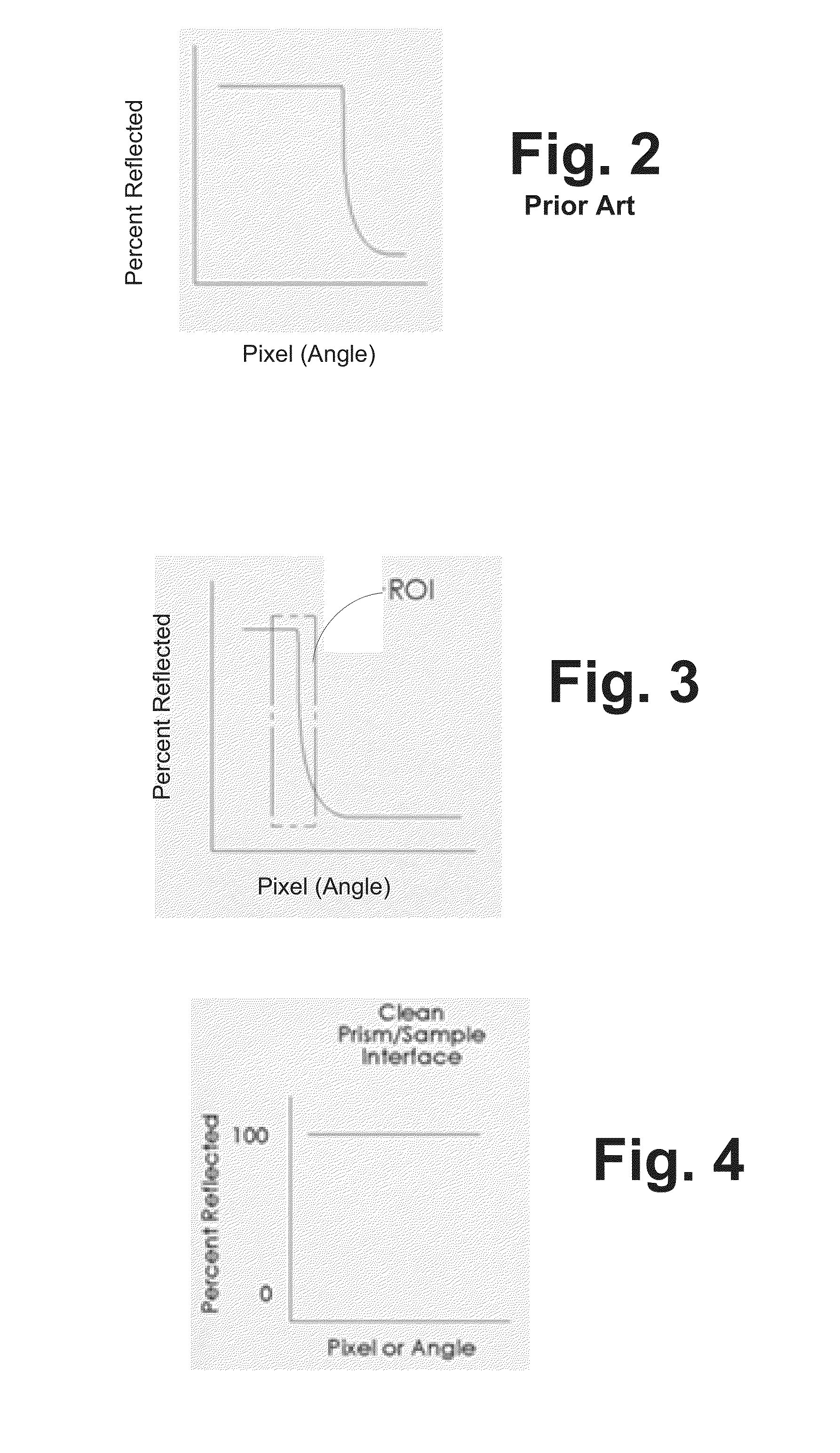
[0018]In addition to determining the refractive index by locating the pixel in the reflectance graph (e.g. FIG. 2) where the transition from total to partial reflection occurs, embodiments in accordance with the present invention also characterize the transition with three additional parameters determined from the pixels and their associated reflectances. After the transition pixel is determined, a window or region of interest (ROI) is established around the transition (see FIG. 3). The three additional parameters are: the average steepness or slope of the graph across the ROI (scaled to 100% for a perfect sample), the maximum reflectance in the ROI, and the minimum reflectance in the ROI. Equivalently, the range and average of reflectance across ROI may be used instead of the maximum and minimum.

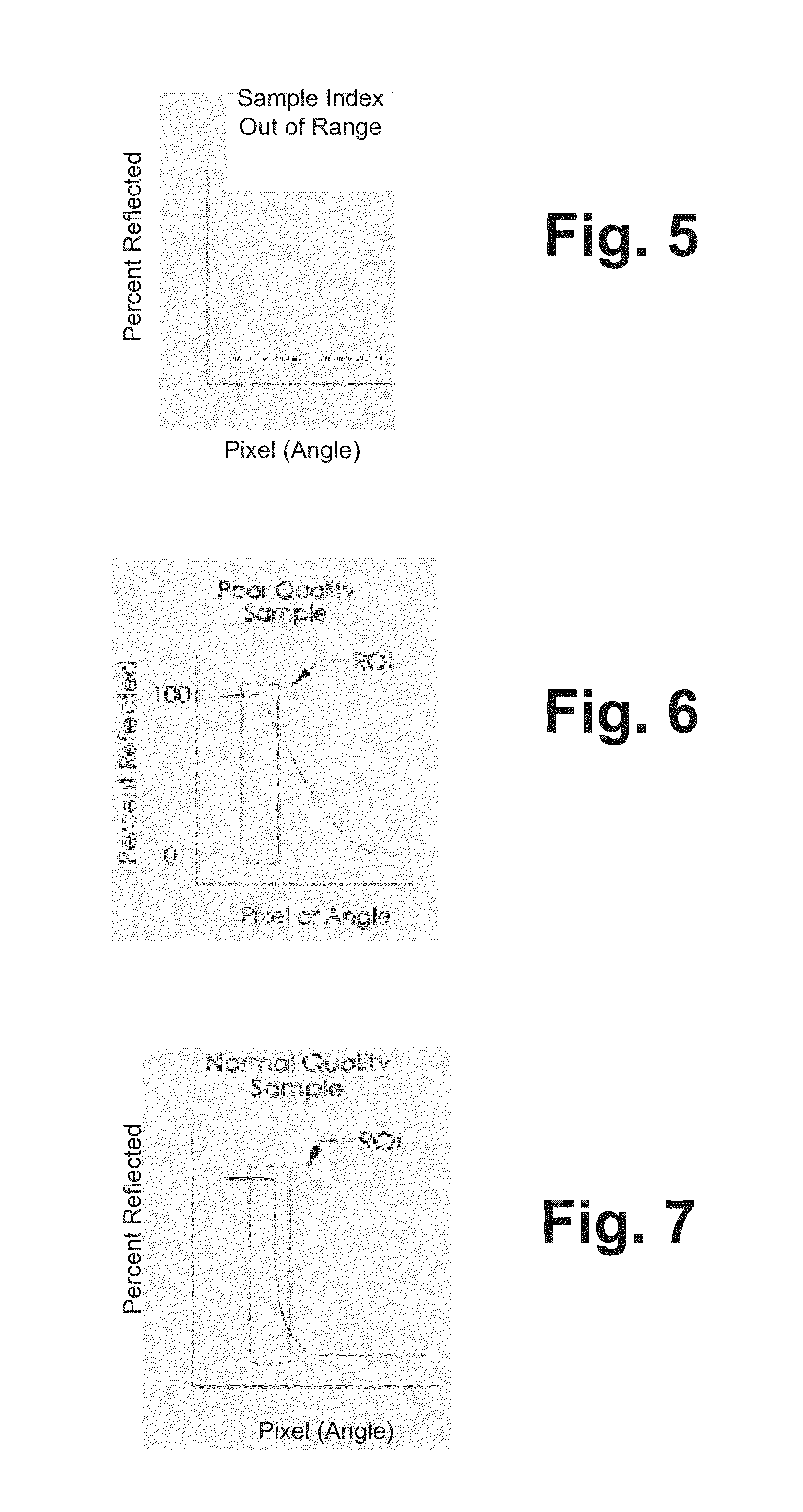
[0019]In a preferred embodiment, these parameters are used to discriminate among four possible states at the prism / sample interface:

[0020]1. Sample Present

[0021]2. Dish Clean

[0022]3. Sample...


PUM

PropertyMeasurementUnit
refractive indicesaaaaaaaaaa
reflectanceaaaaaaaaaa

Abstract

A critical-angle refractometer which utilizes an in image of light reflected from an optical interface with a vessel containing a sample under test to determine an optical property of the sample, sample properties are evaluated to prevent improper testing of the sample. This evaluation includes establishing reflectance information associating the amount of reflection with locations in the image; and utilizing a plurality of properties of the reflectance information to determine if the vessel contains a proper sample under test.

Description

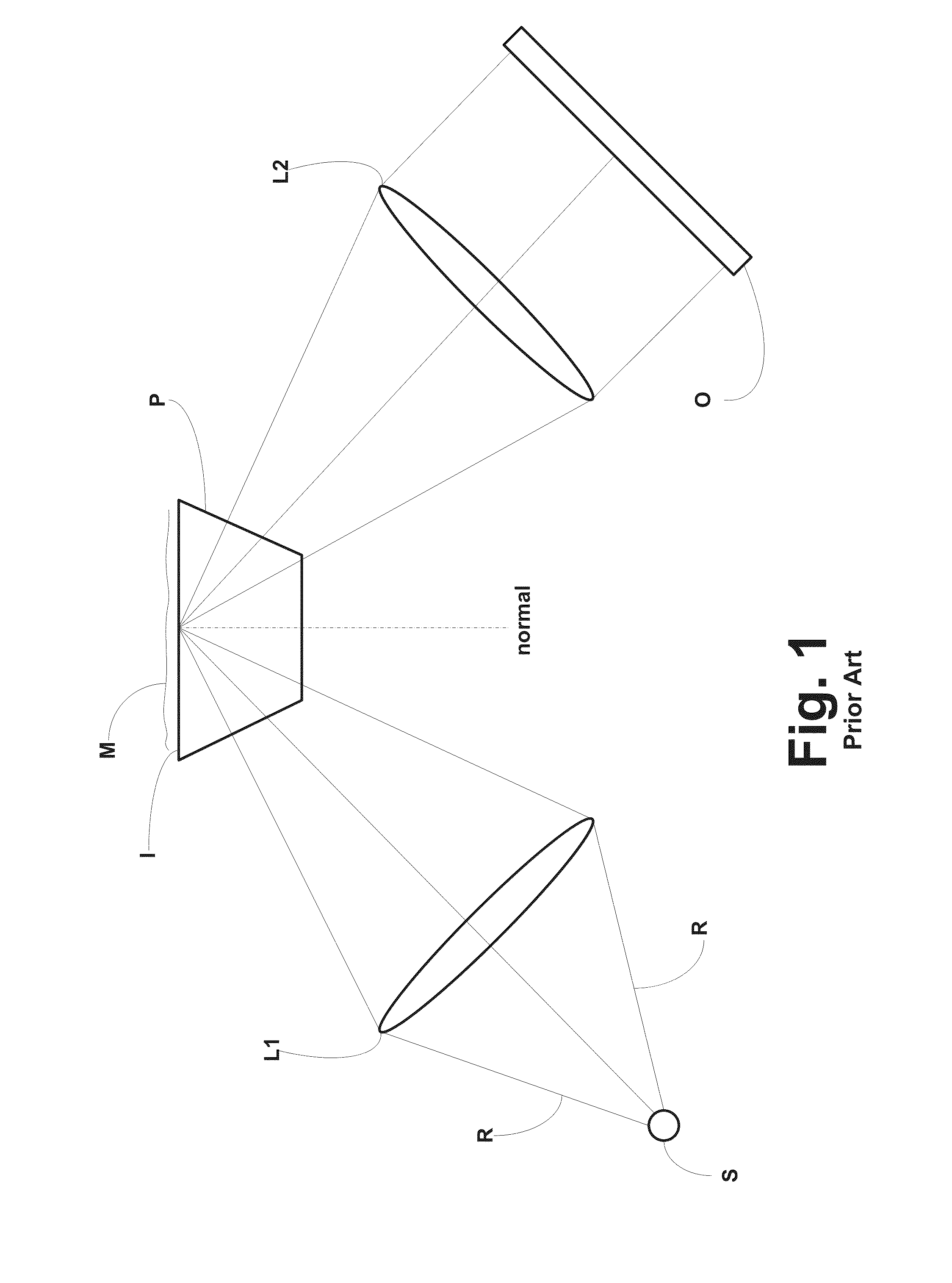
[0001]This application is a Continuation of U.S. patent application Ser. No. 13 / 071,899, filed Mar. 25, 2011, entitled “Critical-Angle Refractometry” then entire disclosure of which is incorporated herein by reference.BACKGROUND OF THE INVENTION[0002]The present invention relates generally to refractometry and, more particularly, concerns a method and apparatus for improving the accuracy and reliability of critical-angle refractometry measurements.[0003]The purpose of a refractometer is to measure the refractive index of a sample material M, for example, a liquid. A prior art critical-angle refractometer is shown schematically in FIG. 1. The liquid sample M is typically contained in a dish in which one surface of an optical prism P, having a high index of refraction, forms the floor of the dish. Rays of light R from a Light Source S are focused by a Lens L1 into prism P. It is characteristic of the interface between two disparate optical media that a light beam entering the interfac...

Claims


Application Information

Patent Timeline
Patent Type & Authority Applications(United States)
IPC IPC(8): G01N21/43
CPCG01N21/43
Inventor WAGNER, JEFF
Owner RUDOLPH RES ANALYTICAL
Learn More