Healing abutment and final abutment for use with dental implant

Inactive Publication Date: 2013-10-31
ROBERTS RYAN EDWARD
View PDF15 Cites 9 Cited by
  • Summary
  • Abstract
  • Description
  • Claims
  • Application Information

AI Technical Summary

Benefits of technology

The present invention provides an improved abutment and method for easily retrieving it if it falls free during the insertion or removal process. A tether is laced through the abutment and enables safe and easy removal or insertion of abutments with minimal training or specialized tools. The use of a tethered abutment increases patient safety during the procedure.

Problems solved by technology

During the insertion and removal of a healing abutment, as well as the insertion of a final abutment, great care is stressed amongst dentists and oral surgeons to not allow the abutment to fall free from their control into the patient's throat and result in complications for the patient.
One serious potential complication when an abutment falls free is asphyxiation, where the fallen abutment prevents the patient from breathing.
Another potential complication from a fallen abutment is aspiration of the abutment by the patient; where instead of blocking the patient's airway, the abutment enters the patient's lungs.
Yet another potential complication from a fallen abutment is when a patient swallows the abutment and the abutment enters the digestive tract, potentially causing digestive complications.
Even with these and other potential complications due to fallen abutments, current healing abutments and final abutments are not configured for easy control and retrieval should the abutment fall from the dentist's control during insertion or removal.
Indeed, for each of the current methods by which a dentist may choose to insert or remove an abutment, even those designed for the improved control or grasp of the abutment, the possibility remains for the abutment to fall free from the dentist's control and not be easily retrievable.
This practice is often uncomfortable or bothersome for the patient.
In addition, if the gauze of the throat pack is not properly positioned at the back of the mouth the opportunity remains for the abutment to pass under or around the gauze placing the patient at risk for severe complications including asphyxiation.
It can also be awkward for the dentist to attempt to retrieve an abutment after it has landed on the gauze.
Moreover, use of gauze can further reduce the available work space for the dentist during the procedure.

Method used


Image

  • Healing abutment and final abutment for use with dental implant
  • Healing abutment and final abutment for use with dental implant
  • Healing abutment and final abutment for use with dental implant

Examples


Embodiment Construction

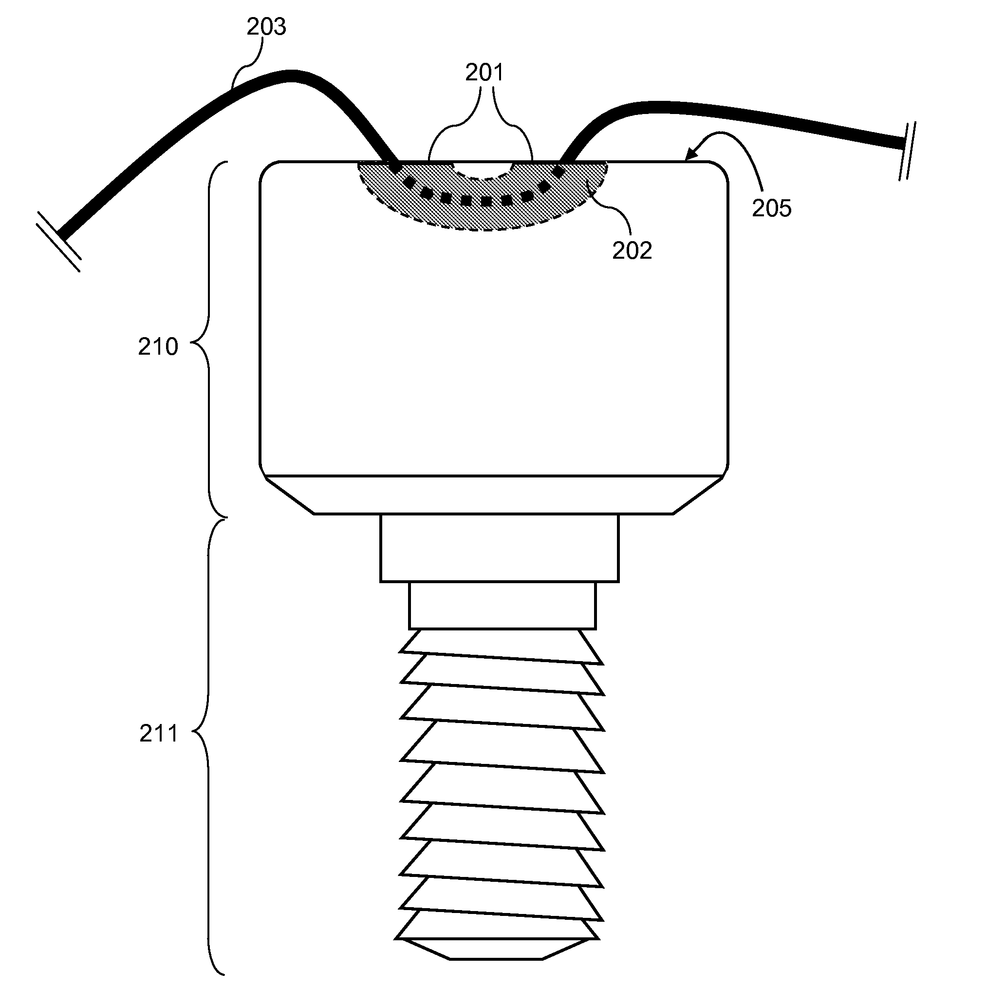
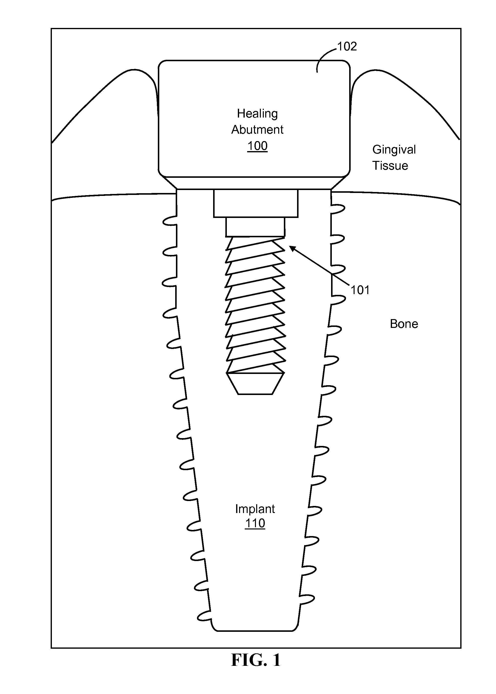
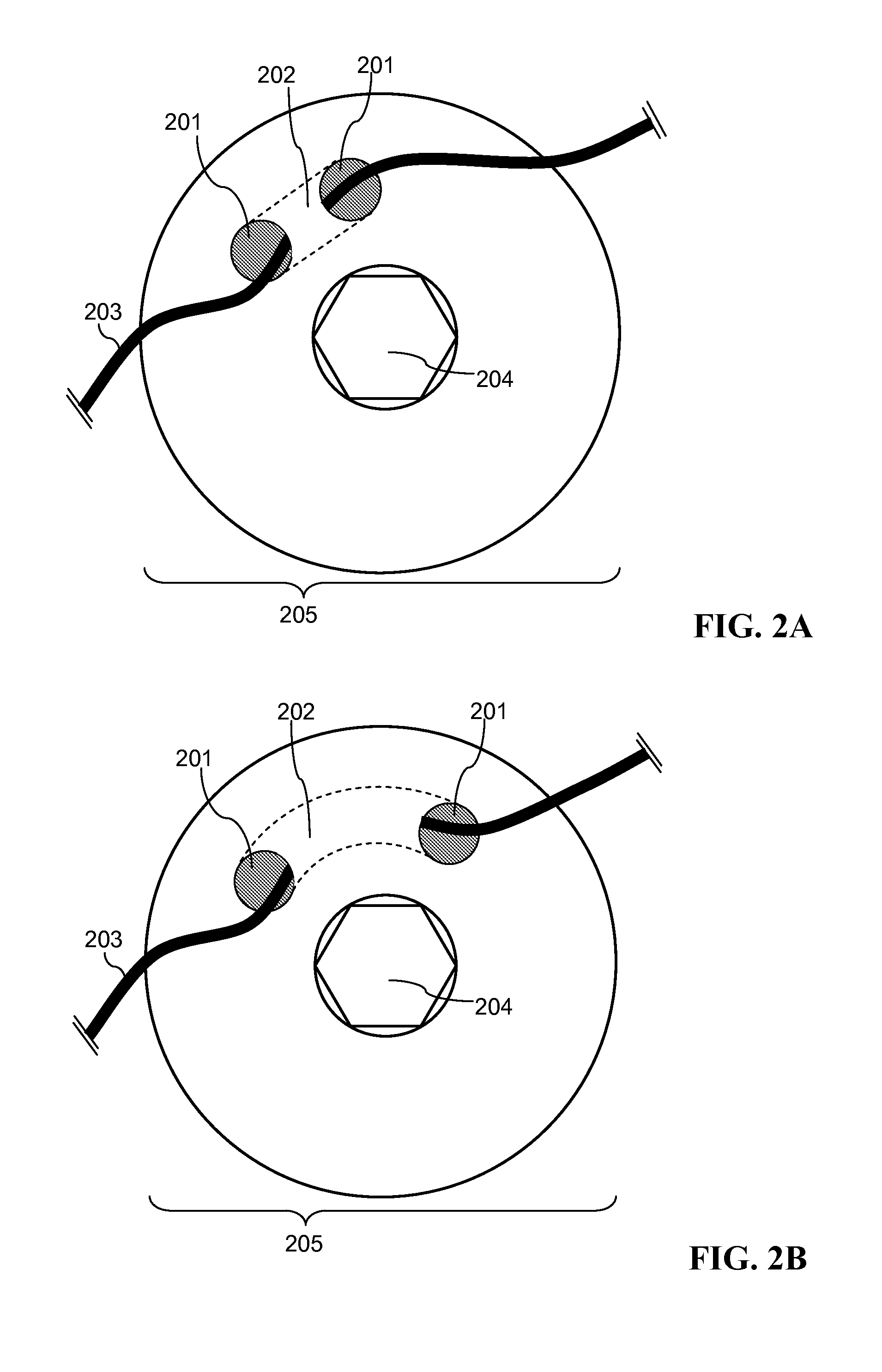
[0020]Embodiments of the invention provide methods and devices for improved dental healing abutments and final abutments for use with dental implants.

[0021]Certain embodiments of the invention enable a dentist to improve the handling of an abutment during insertion and removal even with the challenges presented by the inherent environment of a patient's mouth.

[0022]In particular, a patient's mouth is a confined workspace for a dentist and provides a dentist limited access when the dentist is inserting or removing an abutment. The amount of space available in which a dentist may work (e.g., access) is largely dictated by how far the patient's mandible (lower jaw) can open, as well as the size and shape of the patient's palate (roof of the mouth). Access is especially restricted in the back region of the mouth, approaching the temporomandibular joint where the molars are located. The restricted region provides not only limited work space, but also a limited line of sight and limited a...


PUM


Abstract

Systems and methods of controlling an abutment when inserting or removing the abutment are disclosed. An improved dental abutment is presented that includes a tunnel whereby dental floss may be laced through to serve as a tether for retrieval of the abutment during attachment to or removal from a dental implant.

Description

BACKGROUND OF THE INVENTION[0001]During the insertion and removal of a healing abutment, as well as the insertion of a final abutment, great care is stressed amongst dentists and oral surgeons to not allow the abutment to fall free from their control into the patient's throat and result in complications for the patient.[0002]One serious potential complication when an abutment falls free is asphyxiation, where the fallen abutment prevents the patient from breathing. Another potential complication from a fallen abutment is aspiration of the abutment by the patient; where instead of blocking the patient's airway, the abutment enters the patient's lungs. Yet another potential complication from a fallen abutment is when a patient swallows the abutment and the abutment enters the digestive tract, potentially causing digestive complications.[0003]Even with these and other potential complications due to fallen abutments, current healing abutments and final abutments are not configured for e...

Claims


Application Information

Patent Timeline
IPC IPC(8): A61C8/00
CPCA61C8/005A61C8/0068A61C2008/0084A61C5/48
Inventor ROBERTS, RYAN EDWARD
Owner ROBERTS RYAN EDWARD
Why Eureka
Try Eureka