Digital filter device, digital filtering method and control program for the digital filter device
a digital filter and control program technology, applied in the direction of filters, digital transmission, transmission monitoring, etc., can solve problems such as difficult to keep stable reception, and achieve the effects of high performance, advanced controllability, and distortion compensation
- Summary
- Abstract
- Description
- Claims
- Application Information
AI Technical Summary
Benefits of technology
Problems solved by technology
Method used
Image

Examples
first exemplary embodiment
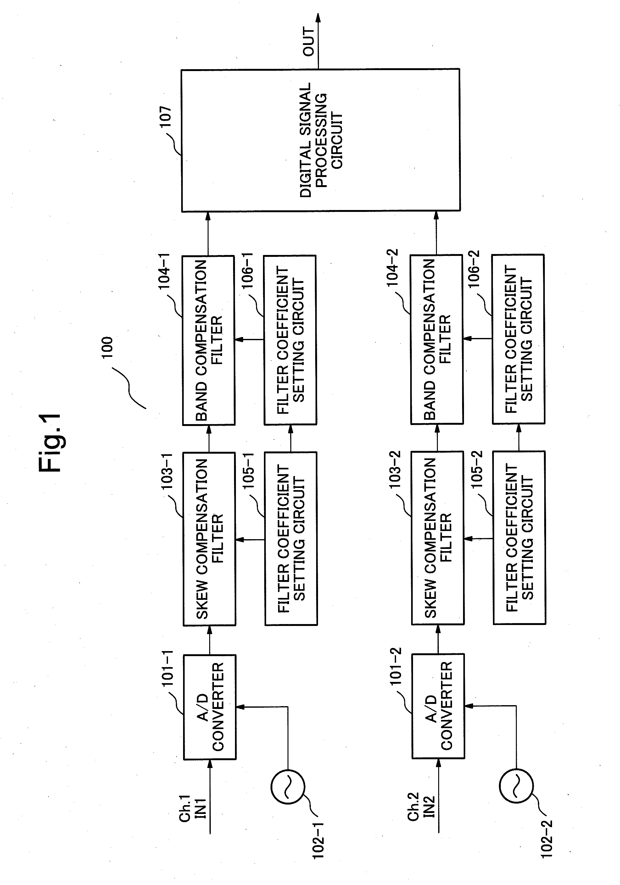
[0032]FIG. 1 illustrates a configuration of a digital receiver related to a first exemplary embodiment of the invention. In FIG. 1, a digital receiver 100 includes an A / D converter 101, an A / D converter identification clock 102, a skew compensation filter 103, and a band compensation filter 104. The digital receiver 100 further includes a filter coefficient setting circuit 105 related to the skew compensation filter, a filter coefficient setting circuit 106 related to the band compensation filter, and a digital signal processing circuit 107. In FIG. 1, when a plurality of units having the same function are arranged, notation for the units in the drawing is distinguished by adding “−1” and “−2” to reference numerals thereof. In following descriptions, if it is unnecessary to particularly distinguish them, for example, “A / D converter 101-1” and “A / D converter 101-2” are described as “A / D converter 101”.
[0033]An operation of the digital receiver 100 related to the first exemplary embod...
second exemplary embodiment
[0054]Next, a second exemplary embodiment of the invention is described below. FIG. 5 is a diagram illustrating a configuration of a digital receiver 500 of the second exemplary embodiment of the invention. In FIG. 5, the digital receiver 500 includes a polarization diversity 90-degree hybrid 501, an optical-electric (O / E) converter 502, an A / D converter 503, a skew compensation filter 504 and a wavelength dispersion compensation filter 505. The digital receiver 500 further includes a filter coefficient setting circuit 506 related to the skew compensation filter, a filter coefficient setting circuit 507 related to the wavelength dispersion filter, and a digital signal processing circuit 508.
[0055]In FIG. 5, when a plurality of units having the same function are arranged, the units are distinguished by adding “−1” and “−2” to reference numerals thereof. In following descriptions, if it is unnecessary to particularly distinguish them, for example, “O / E converter 502-1” and “O / E conver...
third exemplary embodiment
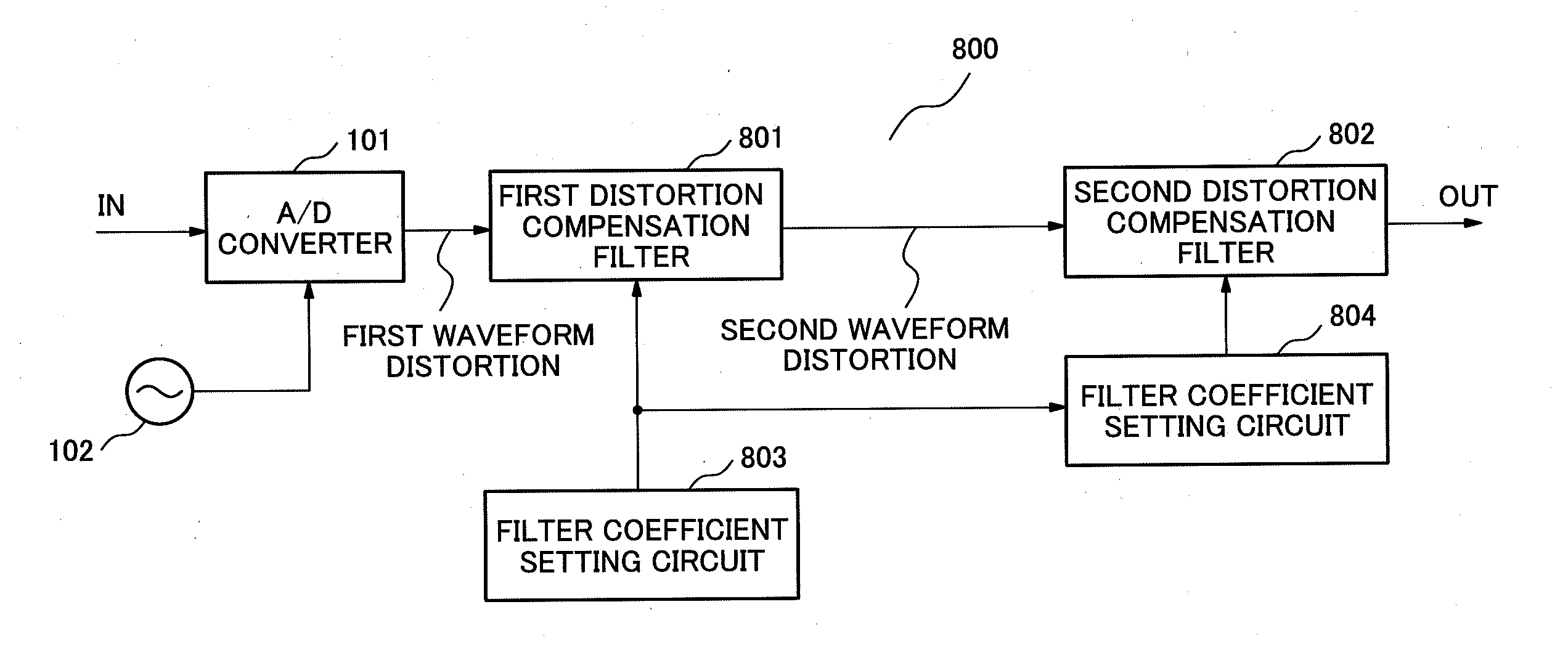
[0066]Next, a third exemplary embodiment of the invention is described. FIG. 8 is a diagram illustrating a digital filter 800 of the third exemplary embodiment of the invention. In FIG. 8, the digital filter 800 includes an A / D converter 101, an A / D converter identification clock 102, a first distortion compensation filter 801 and a second distortion compensation filter 802. The digital filter 800 further includes a filter coefficient setting circuit 803 related to the first distortion compensation filter and a filter coefficient setting circuit 804 related to the second distortion compensation filter.
[0067]An operation of the digital filter 800 is described below. In the digital filter 800 shown in FIG. 8, a signal, which is received by a receiver through a transmission path and is O / E-converted, enters the A / D converter 101. The A / D converter 101 converts the inputted signal, which is an analog electric signal, into a digital signal at the timing in synchronization with the A / D co...
PUM
 Abstract
Description
Claims
Application Information
 - R&D
- Intellectual Property
- Life Sciences
- Materials
- Tech Scout
- Unparalleled Data Quality
- Higher Quality Content
- 60% Fewer Hallucinations
Browse by: Latest US Patents, China's latest patents, Technical Efficacy Thesaurus, Application Domain, Technology Topic, Popular Technical Reports.
© 2025 PatSnap. All rights reserved.Legal|Privacy policy|Modern Slavery Act Transparency Statement|Sitemap|About US| Contact US: help@patsnap.com