Optical Couplers And Methods For Making Same

Active Publication Date: 2013-10-31
NUFERN
View PDF7 Cites 15 Cited by
  • Summary
  • Abstract
  • Description
  • Claims
  • Application Information

AI Technical Summary

Benefits of technology

The present invention provides optical couplers that allow for low-loss signal feed-through and minimal degradation of beam quality for optical radiation propagating through them. Additionally, the optical couplers have a high efficiency in coupling optical radiation from the wide end of the tube to the coupler end face, with a relatively low degradation of the polarization of the optical radiation.

Problems solved by technology

Thus, energy cannot usually be supplied to it directly in the form of electric power.
There are a number of ways of making a pump coupler using free-space optics, but these can typically require painstaking alignment and can be very sensitive to vibration and thermal effects.
All-fiber pump couplers are known, but these can be difficult to fabricate, and often induce unacceptable losses to the pump light and / or the fed-through signal.
Moreover, it can often be desirable for the signal feed-through fiber to pass a signal having a given polarization; many existing coupler designs are incompatible with polarization-maintaining fibers or other polarization-maintaining optical components.

Method used


Image

  • Optical Couplers And Methods For Making Same
  • Optical Couplers And Methods For Making Same
  • Optical Couplers And Methods For Making Same

Examples


example 1

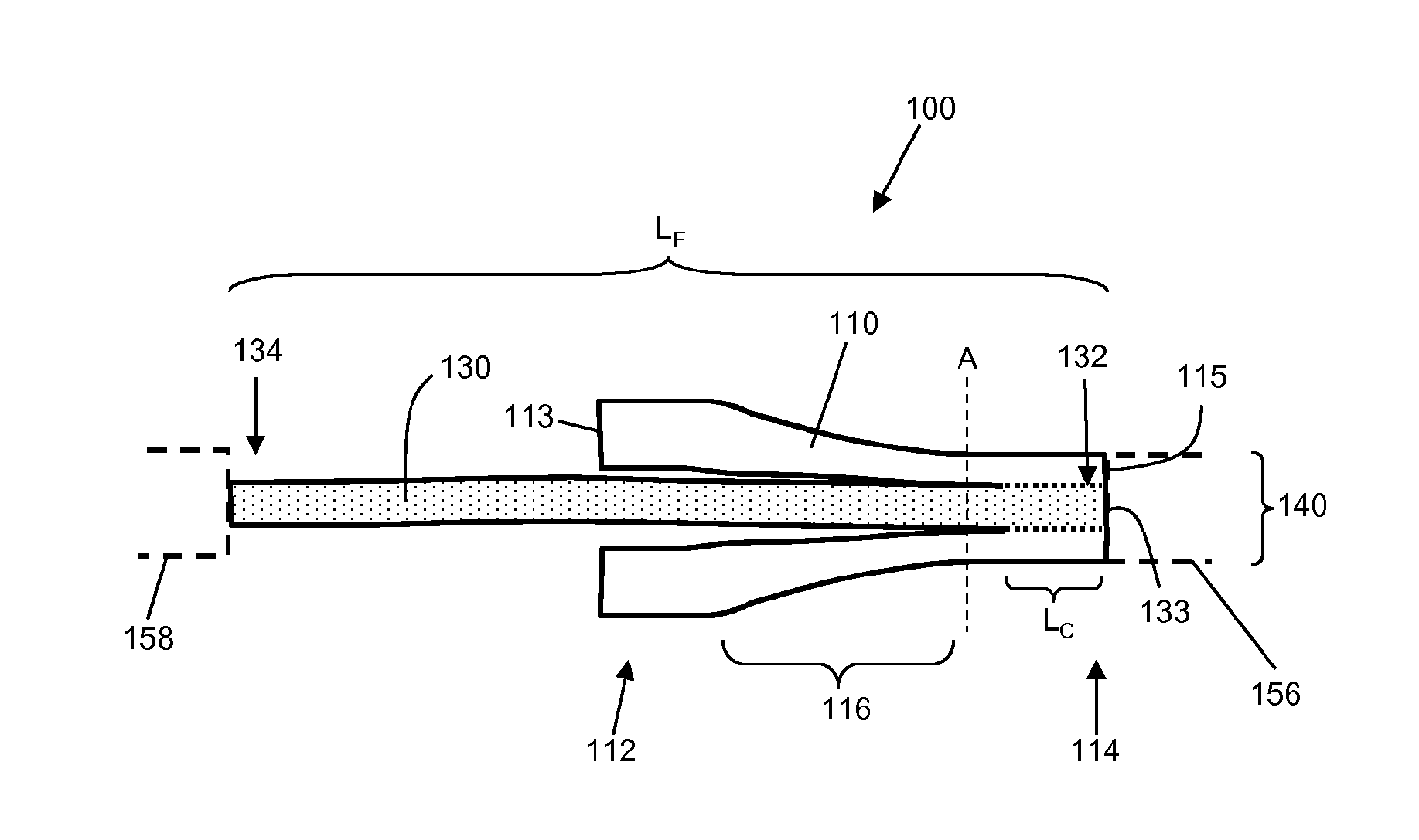
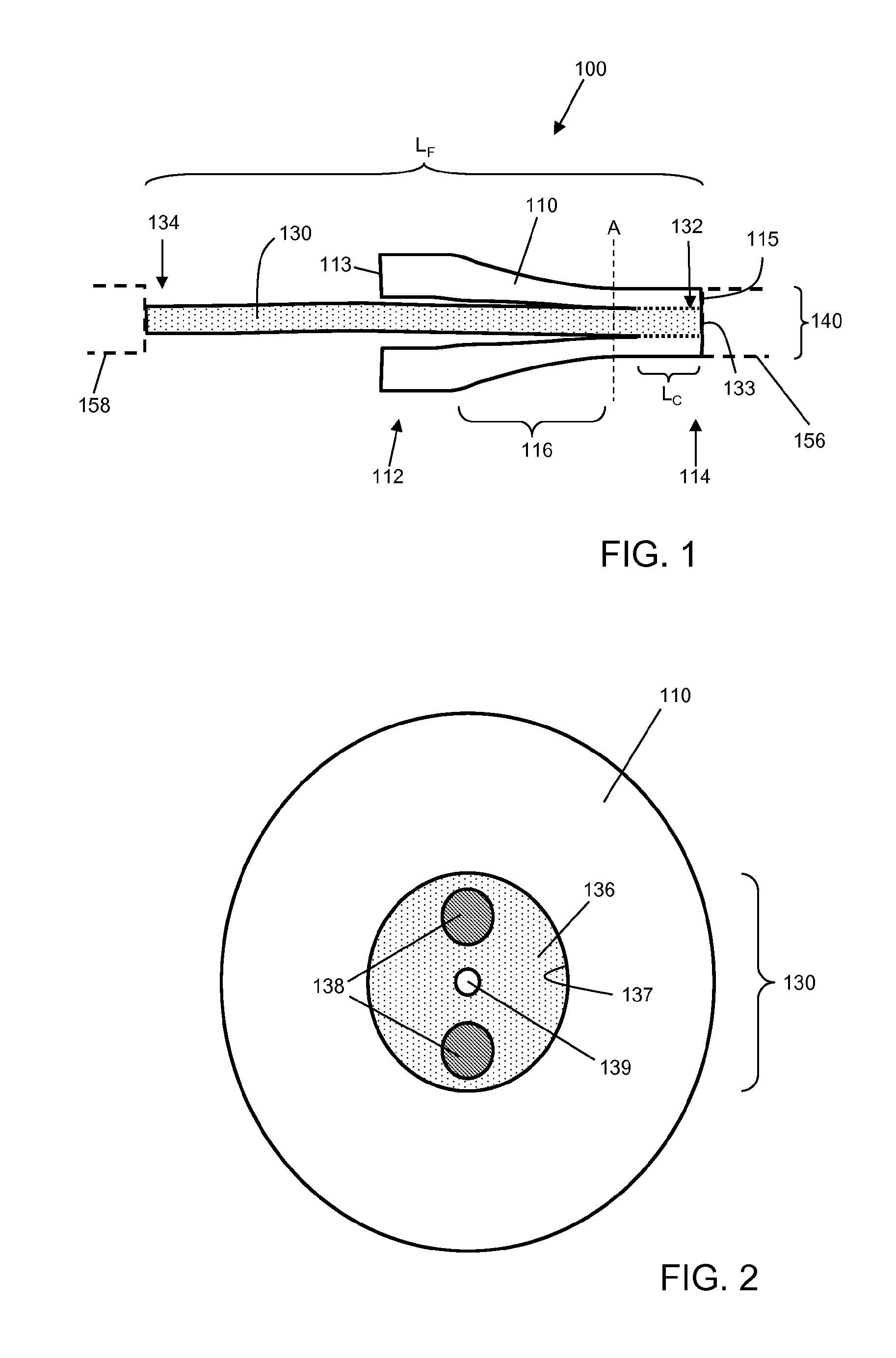
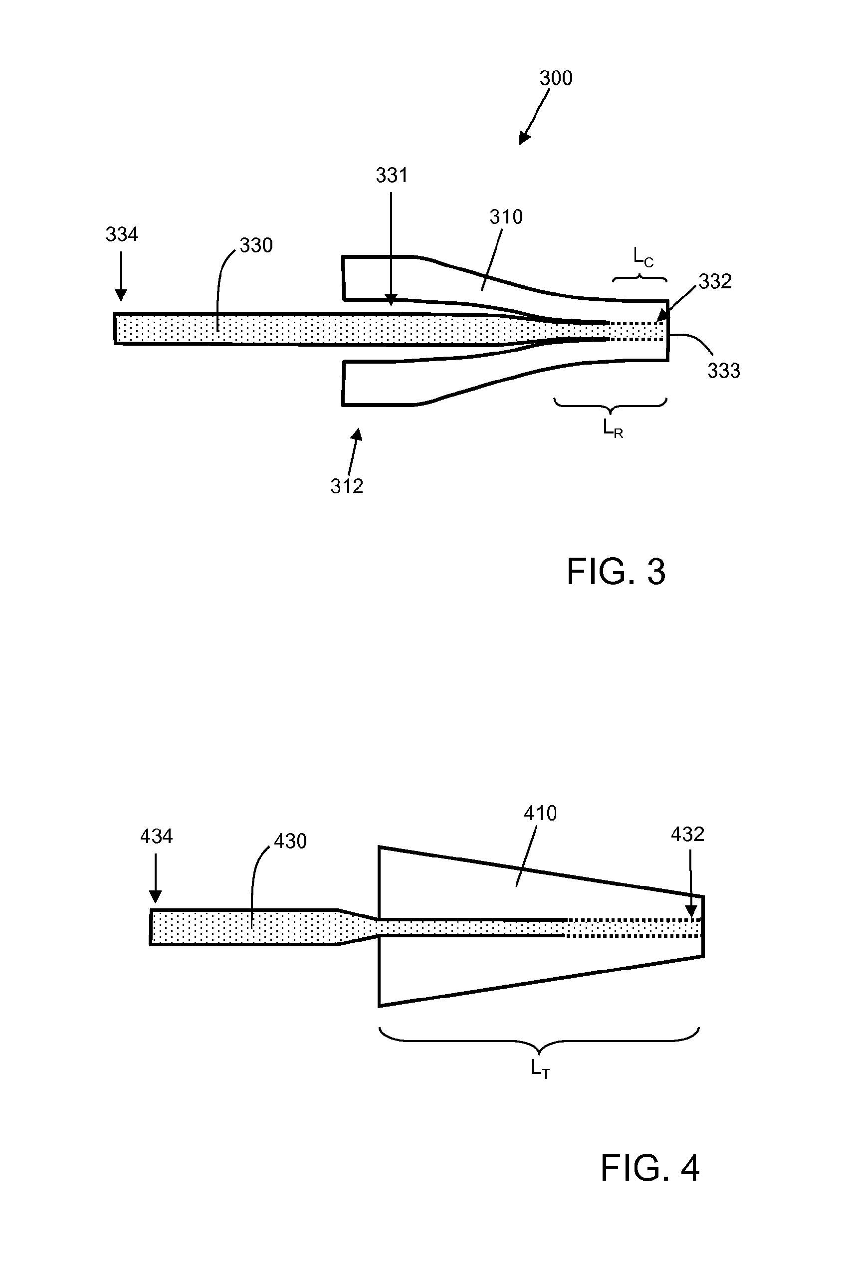
[0090]A glass capillary was drawn with heat to provide a tube as described with respect to FIGS. 1 and 3. The birefringent optical fiber shown in FIG. 13 was etched with HF to just outside the birefringence-inducing elements over a section thereof about 50 mm in length, and disposed in the narrow end of the tube. The narrow end of the tube was heated to collapse around the etched fiber; and cleaved to form an end face. The cleaved end face is shown in FIG. 14.

[0091]The polarization extinction ratio (PER) for the device was measured using the experimental setup shown in FIG. 15. Polarized light at a wavelength of 1 μm with a polarization extinction ratio greater than 30 dB was launched into the input of the device. The input was oriented so that the axis of polarization of the light was aligned with the major axis of the polarization-maintaining input fiber. Two orthogonal states of output light were measured. FIG. 16 provides data for Measurement Point A, before the device. FIG. 17 ...

example 2

[0092]A coupler was made substantially as described above in Example 1. The cleaved endface of the fiber was spliced to 25 / 400 polarization maintaining fiber using a CO2 laser glass working station. The cleaved endface of the coupler, the cleaved endface of the PM fiber, and the fused device are shown in the pictures of FIG. 18. The PER of the overall device was measured substantially as described above with respect to FIG. 15, but measuring the output from the PM fiber. Results are shown in FIG. 19. The PER was measured to be about 18 dB The PER of the input signal was measured to be about 20 dB via a cutback method. Accordingly, the signal is transmitted through the device with very little loss of polarization integrity.

[0093]In the claims as well as in the specification above all transitional phrases such as “comprising”, “including”, “carrying”, “having”, “containing”, “involving” and the like are understood to be open-ended. Only the transitional phrases “consisting of” and “co...


PUM


Abstract

The present invention relates generally to optical waveguides for the transmission of electromagnetic energy. The present invention relates more particularly to optical couplers for coupling optical fibers, and methods for making them. One aspect of the present invention is an optical coupler for use with a polarization-maintaining input optical fiber and a polarization-maintaining output optical fiber. The coupler includes: a tube having a wide end, a narrow end having an end face, and a taper therebetween; a polarization-maintaining feed-through optical fiber having a first end having an end face and a second end, the polarization-maintaining feed-through optical fiber being disposed within the tube from the wide end to the narrow end, at least the narrow end of the tube being fused around a first length of the polarization-maintaining feed-through optical fiber including the first end of the polarization-maintaining feed-through optical fiber to form a coupler end face comprising the end face of the tube and the end face of the first end of the polarization-maintaining feed-through optical fiber. In one aspect of the invention, the polarization-maintaining feed-through optical fiber has an outer diameter no greater than about 200 μm in the region in which the tube is fused around it. In another aspect of the invention, the polarization-maintaining feed-through optical fiber has an outer diameter at the coupler end face no greater than about 75% of the diameter of the polarization-maintaining input optical fiber.

Description

CROSS-REFERENCE TO RELATED APPLICATIONS[0001]The present invention claims the benefit of priority to U.S. Provisional Patent Application Ser. No. 61 / 426,553, filed Dec. 23, 2010, which is hereby incorporated herein by reference in its entirety.BACKGROUND OF THE INVENTION[0002]1. Field of the Invention[0003]The present invention relates generally to optical waveguides for the transmission of electromagnetic energy. The present invention relates more particularly to optical couplers for coupling optical fibers, and methods for making them.[0004]2. Technical Background[0005]Fiber lasers have many attractive properties that make them suitable for various industrial applications. Such properties can include one or more of good beam quality, easy thermal management, compact size, and good efficiency. Fiber lasers are therefore often preferred to conventional types of lasers, such as solid-state and gas lasers. Fiber lasers are able to produce optical output in the several kW range with ex...

Claims


Application Information

Patent Timeline
IPC IPC(8): G02B6/27B29D11/00
CPCG02B6/274B29D11/00711G02B6/2843H01S3/06712H01S3/0675H01S3/07H01S3/094011H01S3/094019H01S3/09408G02B6/02109
Inventor MAJID, IMTIAZWANG, CHIH-HAOTANKALA, KANISHKA
Owner NUFERN
Why Eureka
Try Eureka