Air Break Electrical Switch Having a Blade Open/Closed Indicator

Active Publication Date: 2013-10-31
HUBBELL POWER SYST INC
View PDF3 Cites 11 Cited by
  • Summary
  • Abstract
  • Description
  • Claims
  • Application Information

AI Technical Summary

Benefits of technology

This invention is an electrical switch that has a frame, a first electrical terminal with blade contacts, and a blade support housing that can pivot about a first and a second axis. The switch also has a toggle mechanism with two toggle members and a biasing member that engages the two toggle members to prevent the blade from moving in a certain direction. When the blade reaches the closed position, the toggle mechanism causes the blade to move in the other direction, causing it to contact the first electrical terminal and make the electrical connection.

Problems solved by technology

These low-closing force switches are not without drawbacks, however.
In particular, the blades of previous low-closing force switches are capable of pivoting about their longitudinal axis prematurely.
Second and when closing the switch, the blade may initially bounce off the distal electrical terminal and allow the blade to rotate about its longitudinal axis before it is properly seated in the electrical terminal.
In both of these cases, the switch cannot be subsequently closed using the operating mechanism.

Method used


Image

  • Air Break Electrical Switch Having a Blade Open/Closed Indicator
  • Air Break Electrical Switch Having a Blade Open/Closed Indicator
  • Air Break Electrical Switch Having a Blade Open/Closed Indicator

Examples


Embodiment Construction

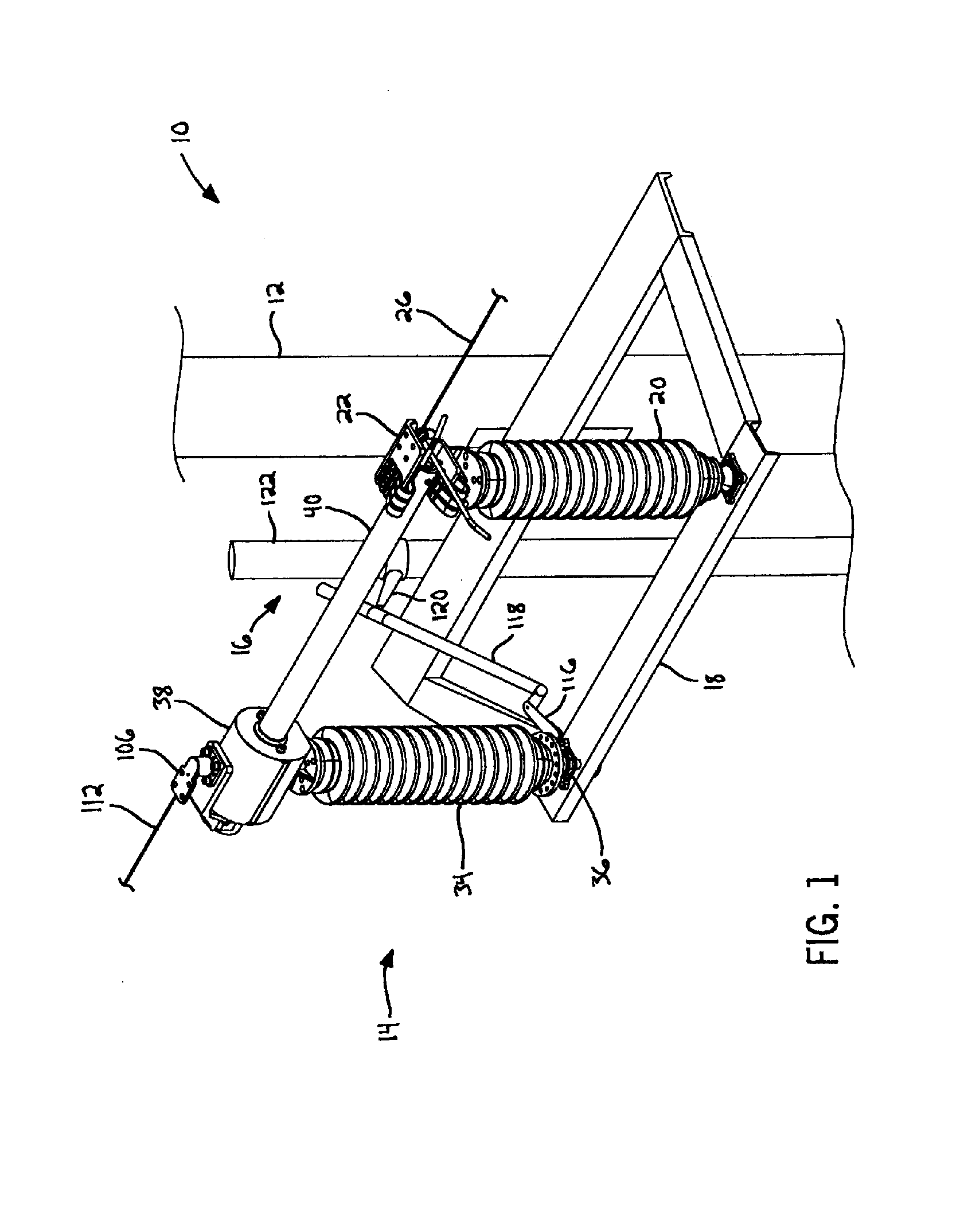
[0026]Referring first to FIG. 1, a high voltage / high current electrical or air break switch 10 of the present invention may be supported by many types of appropriate utility structures, such as a utility pole 12. In general, the switch 10 includes one or more upper switches 14 disposed above the ground and an operating mechanism 16 extending from the upper switch 14 toward the ground. The operating mechanism 16 may be driven by an electrical technician on the ground to move the upper switch 14 between different operating positions. Unlike previous switch designs, the present switch 10 includes features that effectively inhibit a conductive blade 40 from prematurely pivoting to a position in which it is configured to contact a distal terminal. These aspects are described in further detail in the following paragraphs.

[0027]Referring to FIGS. 1-4, the general structure of the upper switch 14 will first be described. The upper switch 14 includes a support frame 18 fixedly connected to t...


PUM


Abstract

An electrical switch includes a pivotally supported blade, a toggle mechanism, and an operating mechanism. The operating mechanism is drivable in a first direction to pivot the blade about a first axis and toward a closed blade position. When pivoting toward the closed blade position, the toggle mechanism inhibits the blade from pivoting about a second axis. Upon reaching the closed blade position, continued motion of the operating mechanism in the first direction causes the toggle mechanism to pivot the blade about the second axis toward a closed contact position. In the closed contact position, the blade contacts at least one blade contact to electrically connect the blade and a first electrical terminal.

Description

CROSS-REFERENCE TO RELATED APPLICATION[0001]This application claims the benefit of U.S. Provisional Patent Application No. 61 / 434,263 filed Jan. 19, 2011, the disclosure of which is hereby incorporated by reference in its entirety.STATEMENT CONCERNING FEDERALLY SPONSORED RESEARCH OR DEVELOPMENT[0002]Not applicable.FIELD OF THE INVENTION[0003]This invention relates to a high voltage / high current air break switch that rotates about multiple axes to engage a distal electrical terminal.BACKGROUND OF THE INVENTION[0004]High voltage / high current air break switches typically include an elongated conductive contact or “blade” that is locked or otherwise secured to a distal electrical terminal during operation to ensure that the components remain in contact. Relatively large forces must be established and overcome to move the blade into a locking position to assure a stable conductive connection.[0005]Some previous designs provided blades that could be closed by exerting relatively low force...

Claims


Application Information

Patent Timeline
IPC IPC(8): H01H31/28
CPCH01H31/28H01H1/52H01H31/30H01H2031/286H01H31/00H01H31/026
Inventor RHEIN, DAVID A.
Owner HUBBELL POWER SYST INC
Why Eureka
Try Eureka