Heater core assembly

Inactive Publication Date: 2008-10-30
BEHR AMERICA
View PDF8 Cites 3 Cited by
  • Summary
  • Abstract
  • Description
  • Claims
  • Application Information

AI Technical Summary

Benefits of technology

[0005]The clamp can be made of plastic, for example, and grips the heater tubes and the tube stub in all directions. Most importantly, the clamp prevents the heater tube from pivoting at the connection to the heater core which can ultimately lead to metal fatigue and a rupture of the connection to the heater core. The clamp of the heater core assembly is configured as two bracket halves hinge connected by a living hinge and can be made using injection molding techniques. The clamp allows for quick and easy installation thereof and includes a latching device for self locking which eliminates the need for any additional fasteners.

Problems solved by technology

Most importantly, the clamp prevents the heater tube from pivoting at the connection to the heater core which can ultimately lead to metal fatigue and a rupture of the connection to the heater core.

Method used


Image

  • Heater core assembly
  • Heater core assembly
  • Heater core assembly

Examples


Embodiment Construction

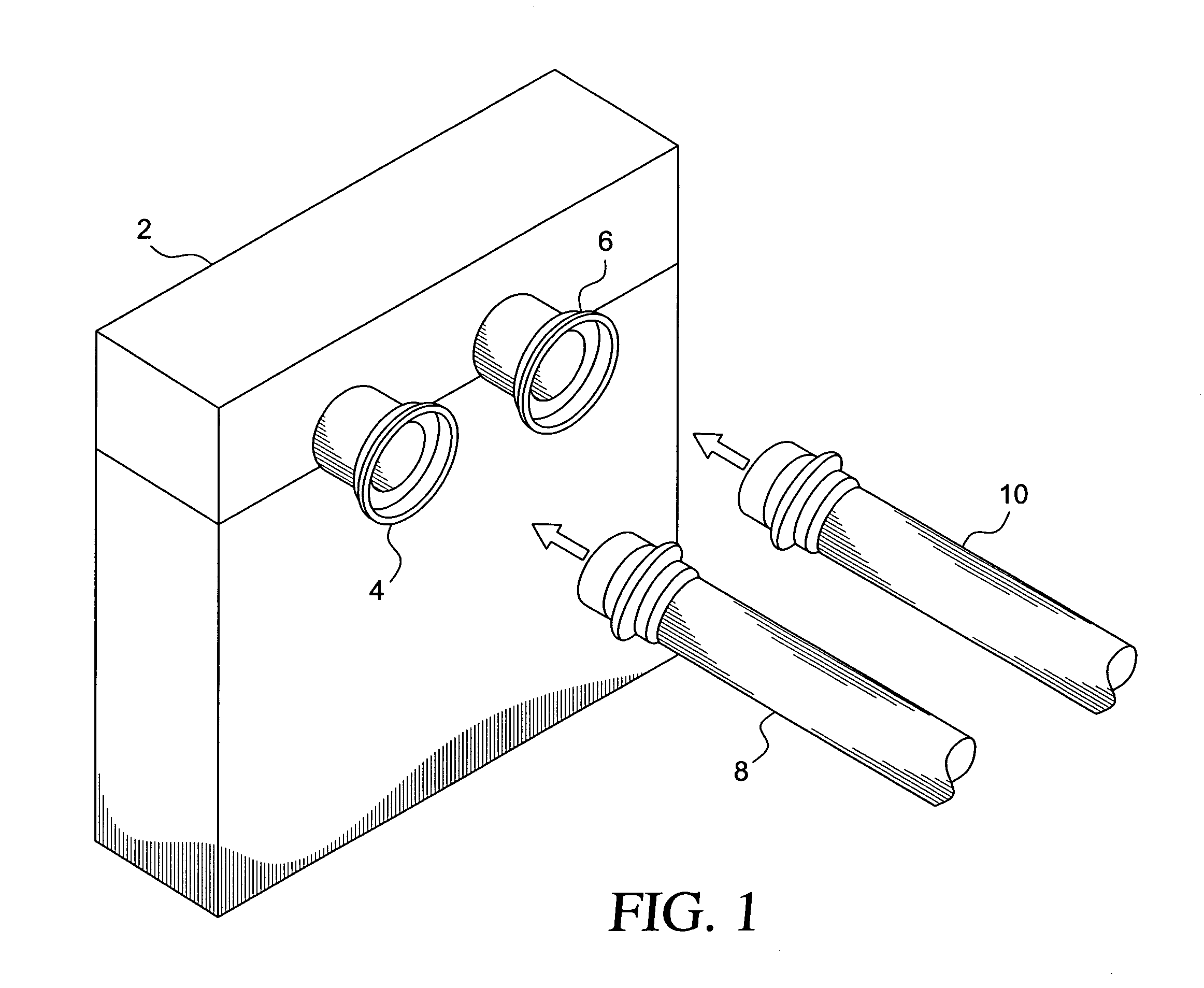
[0014]FIG. 1 shows a heater core 2 having two tube stubs in the form of two core cups 4 and 6 brazed to the heater core. The two core cups (4, 6) define passages for coolant into and out of the tubing of the heater core. Two heater tubes 8 and 10 are shown about to be slip fitted into the core cups 4 and 6, respectively.

[0015]FIG. 2 is a section plan view which also shows the heater tubes 8 and 10 about to be placed in position against the respective core cups 4 and 6. The clamp 12 is shown in phantom outline to show its position after the heater tubes 8 and 10 are in place.

[0016]The next step for securing the heater tubes 8 and 10 to the core cups 4 and 6 is shown in FIG. 3. Here, a clamp 12 is in the open position and readied for placement over the respective stub / tube pairs. The clamp 12 is first placed in position adjacent the heater core as indicated by arrow 9 and then the clamp is closed as indicated by arrow 11.

[0017]The clamp 12 includes a bracket half 14 defining a plane. ...


PUM


Abstract

A heater core assembly includes a heater core having two tube stubs projecting therefrom. Two heater tubes engage the two tube stubs, respectively, to define respective abutting interfaces therewith. A clamp couples the heater tubes to corresponding ones of the tube stubs. The clamp includes a first bracket half having two arcuately-shaped openings formed therein for accommodating the stub / tube pairs at the abutting interfaces to permit the stub / tube pairs to extend transversely to the clamp. A second bracket half is hinge connected to the first bracket to permit opening and closing of the clamp. The second bracket half likewise has two arcuately-shaped openings to accommodate the stub / tube pairs when the second bracket half is pivoted onto the first bracket half. The clamp snugly holds the stub / tube pairs when closed. The first and second bracket halves have a thickness measured in the longitudinal direction of each of the stub / tube pairs to extend beyond the abutting interfaces. This permits the clamp to hold the stub / tube pairs at both sides of each of the abutting interfaces thereby laterally supporting the stub / tube pairs and preventing bending at the interfaces. A latch latches the first bracket half and the second bracket half to each other when the clamp is closed.

Description

FIELD OF THE INVENTION[0001]The invention relates to a heater core assembly wherein heater tubes are connected to a heater core.BACKGROUND OF THE INVENTION[0002]Heater tubes are connected to a heater core, for example, in HVAC systems in motor vehicles. Present day heater core connections often consist of simply brazing the heater tubes to the heater core. Alternatively, the heater core connection can include metal clips that slide over the connection. The problem associated with these connections is that the clips can slide or bend and allow the seal to be broken when the heater tubes are bent or deflected. In the case where the heater tubes are brazed to the heater core, metal fatigue can lead to an early rupture of the connection. The conventional connection of the heater tubes to the heater core holds the tubes in only two directions and provides no effective lateral support.SUMMARY OF THE INVENTION[0003]In view of the above, it is an object of the invention to provide a heater ...

Claims


Application Information

Patent Timeline
IPC IPC(8): F28F7/00
CPCF28F9/0246F28F2275/08F28F2275/085B60H1/00571F16L37/56
Inventor TCHANG, MICHAELDARGEL, STEVENFORSYTH, DAVID
Owner BEHR AMERICA
Why Eureka
Try Eureka