Image forming apparatus

a technology of forming apparatus and molds, which is applied in the direction of instruments, doors/window fittings, constructions, etc., can solve the problems of increasing molds, creating level differences on the outer surface, and increasing general-purpose property costs

Inactive Publication Date: 2013-10-31
CANON KK
View PDF7 Cites 11 Cited by
  • Summary
  • Abstract
  • Description
  • Claims
  • Application Information

AI Technical Summary

Problems solved by technology

Using a single type of hinge, however, creates level differences on an outer surface.
Further, increase of the number of component parts results in increasing molds for mass production, and also becoming a factor to increase costs in general-purpose property.
There have also been disadvantages in that if the problems are to be solved by other parts, such as a framework, it is necessary to apply complex bending or draw forming processes, which are technically difficult, and yet make difficult to obtain accuracy.

Method used


Image

  • Image forming apparatus
  • Image forming apparatus
  • Image forming apparatus

Examples


embodiment 1

[0051]First, a description will be made of a structure of the first embodiment of the image forming apparatus according to the present invention, referring to FIGS. 1 to 12.

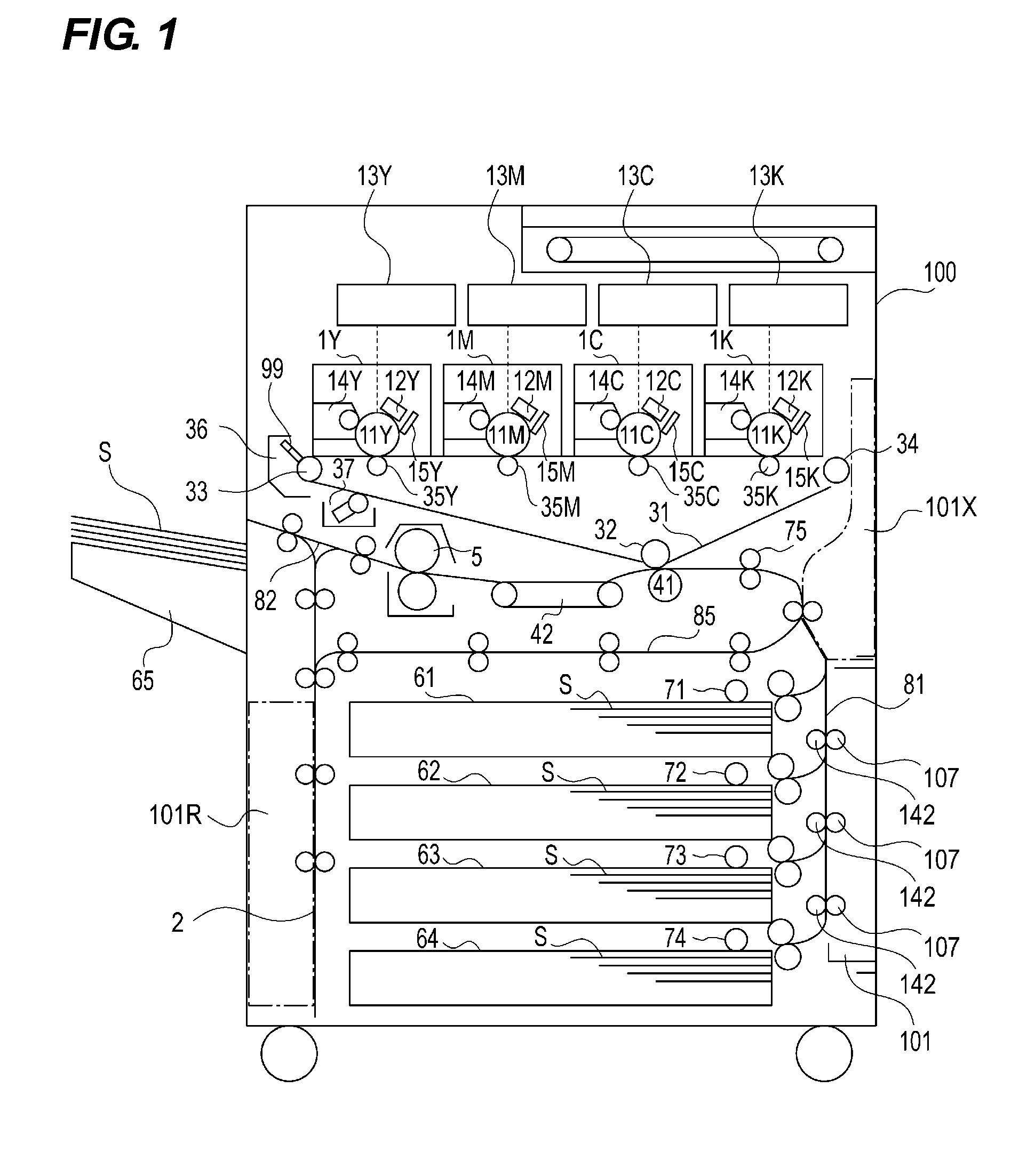
[0052]FIG. 1 is a cross-sectional explanatory view illustrating the image forming apparatus according to the present invention.

[0053]The image forming apparatus 100 illustrated in FIG. 1 is an apparatus for forming images, adopting a tandem-type intermediate transfer method in which image forming portions 1Y, 1M, 1C, 1K are arranged in series on a horizontal portion of an intermediate transfer belt 31. Then, according to an image information (signal) transmitted from an external device, a full-color image is formed on a sheet S by way of an electro photographic system. In the following description, the image forming portions 1Y, 1M, 1C, 1K may be represented with an image forming portion 1. Other image forming process members are also described in the same manner.

[0054]In the image forming portion 1, a toner imag...

embodiment 2

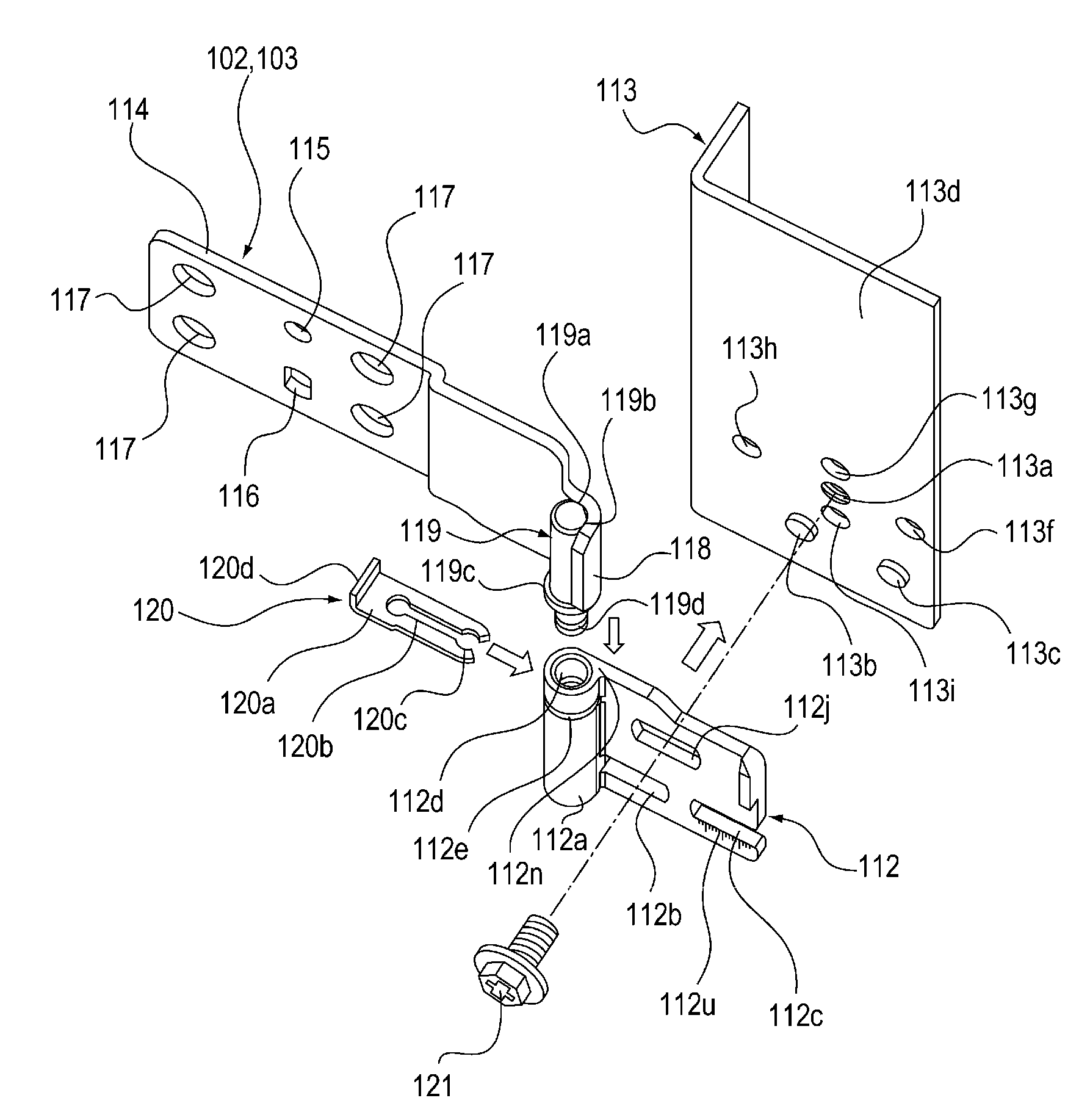
[0137]Next, a description will be made of a structure of a second embodiment of the image forming apparatus according to the present invention with reference to FIGS. 13 to 21. Portions structured in the same way as those of the first embodiment described above are given by the same reference numerals to omit those descriptions.

[0138]In the structure according to the first embodiment as described above, the separation distance (joint height) of the mounting bearing surface of the fixed-side hinge plate 112 with respect to the mounting bearing surface 113d of the rear side plate 113 can be chosen between two different levels of separation distances (joint height). In a structure according to the second embodiment, the separation distance (joint height) of the mounting bearing surface of the fixed-side hinge plate 112 with respect to the mounting bearing surface 113d of the rear side plate 113 can be chosen among three different levels of separation distances (joint height).

[0139]As i...


PUM


Abstract

A hinge mechanism arranged between a main body and a door, and openably and closably supporting the door, comprising: a fixed-side hinge plate disposed at the main body; and a movable side hinge plate disposed at the door, wherein the fixed-side hinge plate includes a bearing surface and a plurality of projection portions projected from the bearing surface, and the fixed-side hinge plate is mountable to (1) a first mounting portion of the main body, having holes through which the projection portions can be inserted, and being capable of abutting to the bearing surface, and (2) a second mounting portion of the main body, being capable of abutting to end surfaces of the plurality of projection portions.

Description

BACKGROUND OF THE INVENTION[0001]1. Field of the Invention[0002]The present invention relates to an image forming apparatus, such as a copying machine and a printer.[0003]2. Description of the Related Art[0004]In an image forming apparatus in which a door is openably and closably mounted via a hinge portion, there is one in which the door is opened to open a sheet conveyance path.[0005]A variety of methods, such as clamping screw, removing a rotation axis, separable hinge with a removable and insertable rotation axis, are used for a structure of a detachable door.[0006]In addition, there is a separable hinge having a lock mechanism which can separate the hinge only when moving to an end portion of rotation.[0007]Japanese Utility Model Laid-Open No. 63-191802 discloses a hinge having a slit in a hinge shaft in which a plate-like axial pin is insertably and removably attached.[0008]Japanese Patent Laid-Open No. 2007-211490 discloses a pin-removal stopper attached to a hinge pin.[0009]...

Claims


Application Information

Patent Timeline
Patent Type & Authority Applications(United States)
IPC IPC(8): E05D7/10E05D3/02
CPCE05D7/1044E05D3/02E05D5/128E05D7/04E05D2007/0484E05Y2900/132G03G21/00
Inventor YAMAGUCHI, YOSHIMASU
Owner CANON KK
Why Eureka
Try Eureka