
Motor driven lock for truck door

a technology for truck doors and locks, applied in the field of motor driven locks for truck doors, can solve the problems of unsatisfactory torque development of latch members, unfavorable latching, and the inability to quickly and reliably achieve the effect of preventing movement of latch members

Inactive Publication Date: 2013-10-24
BABACO ALARM SYST
View PDF3 Cites 37 Cited by
  • Summary
  • Abstract
  • Description
  • Claims
  • Application Information

AI Technical Summary

Benefits of technology

The patent text describes a device that prevents a latch from moving when it is blocked or interference occurs. The device includes springs that compress when the latch is blocked and protect the device when the latch cannot move. Additionally, the device has two limit switches that de-energize the motor when the latch contacts the switches. The technical effect of this device is to ensure safe and reliable functioning of the latch mechanism.

Problems solved by technology

However, conventional motorized locks suffer from various disadvantages, including being unable to develop sufficient torque to quickly and reliably move the latch member, as well as the inability to prevent vibrations resulting from the normal operation of the truck from causing displacement of the drive nut and hence unwanted movement of the latch member.
Further, they lack a mechanism for reliably protecting the motor from burning in the event that the path of movement of the latch member is blocked.

Method used


Image

  • Motor driven lock for truck door
  • Motor driven lock for truck door
  • Motor driven lock for truck door

Examples


Embodiment Construction

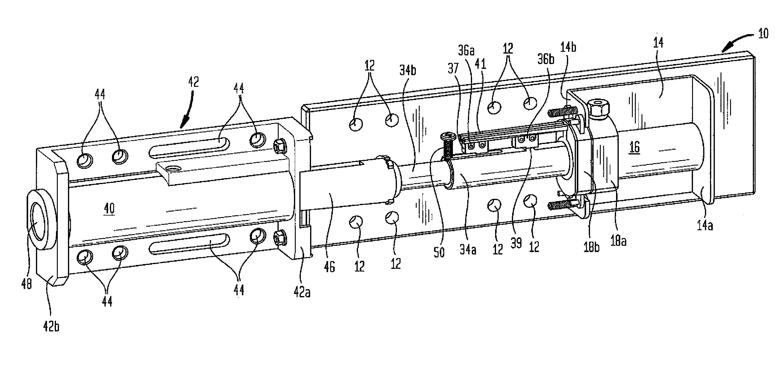
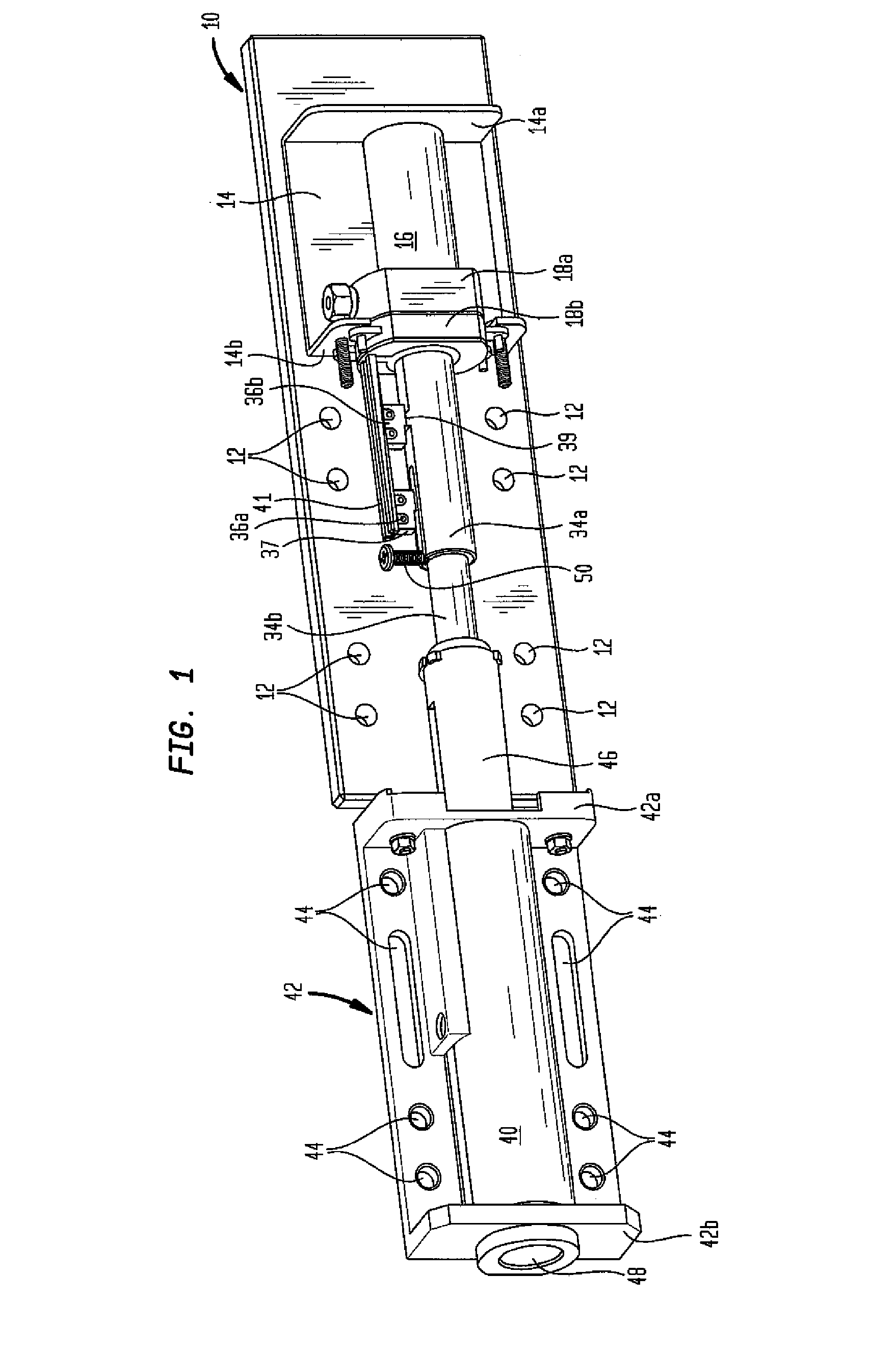
[0040]As seen in FIG. 1, the motor driven lock of the present invention includes a base 10 designed to be affixed to the interior surface of a truck door (not shown) by means of screws (not shown). Base 10 has holes 12 for mounting a guide member, as explained below. Permanently fixed to the surface of base 10 is a generally “U” shaped bracket 14, including a rear wall 14a and a front wall 14b, the latter having a central opening.

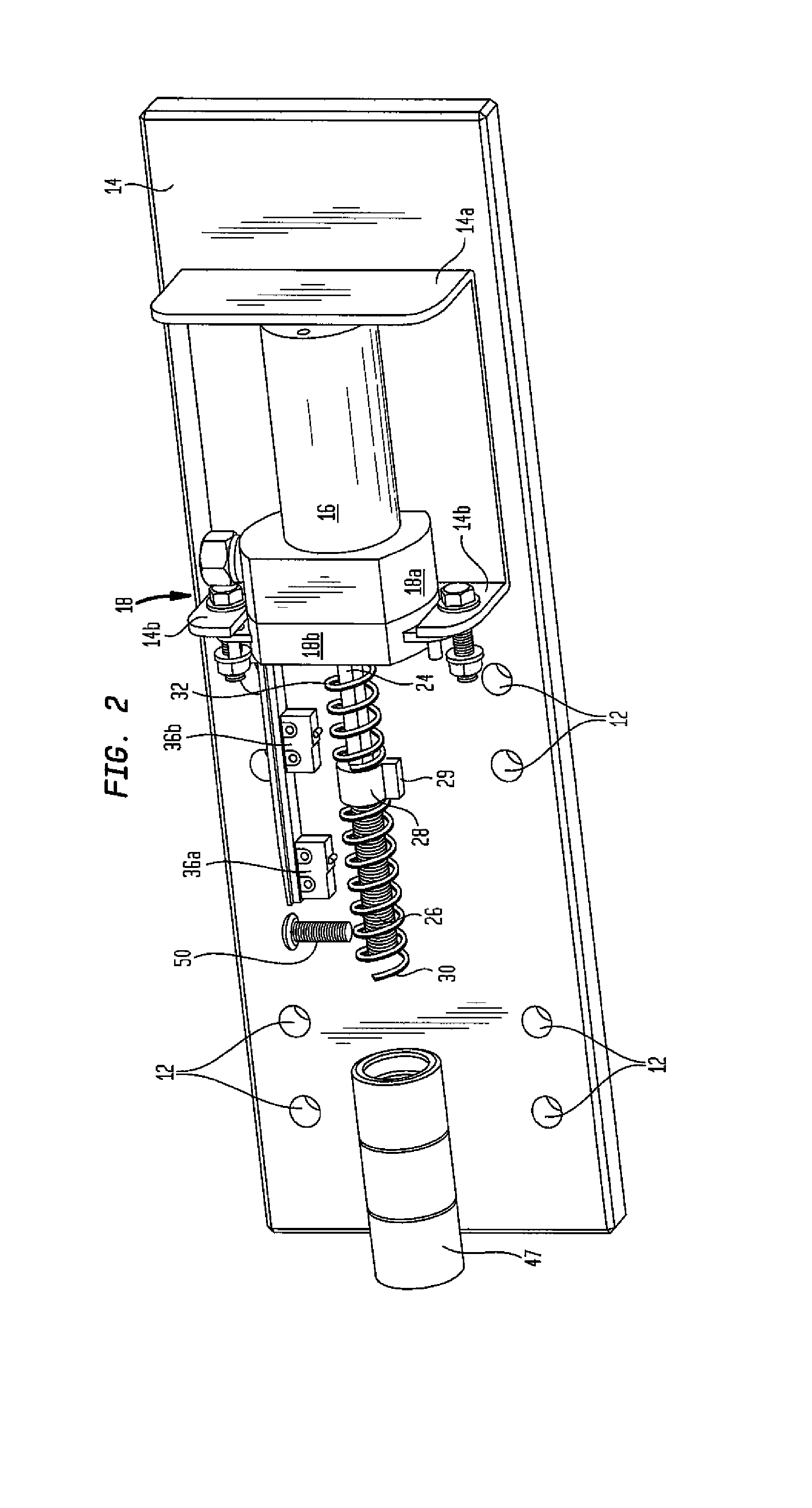
[0041]Mounted between walls 14a and 14b of bracket 14 is a reversible electric motor 16. A gear box 18, including a housing formed of parts 18a, 18b which enclose a set of two speed reduction gears 20a, 20b (see FIG. 3). Gear box 18 is mounted on bracket front wall 14b, within the central opening of front wall 18b, and is connected to the bracket front wall by screws.

[0042]Gear box 18 is connected between the output shaft of motor 16 and a rotatable drive shaft 24. Gears 20 reduce the speed of the motor output shaft and increase the torque applied to the dr...


PUM


Abstract

The lock includes a latch member moveable between a retracted position where the truck door can be moved and an extended position where movement of the door is prevented. The latch member is moved by a reversible motor connected to drive a threaded screw through a set of speed reduction gears. An internally threaded drive nut is moveable along the screw. The drive nut has a radially extending protrusion which engages a slot formed in the latch member. Limit switches are tripped by the latch member at either end of its path of movement. The drive nut is situated between two springs. A control circuit is provided to regulate the energization of the motor and other functions of the lock.

Description

CROSS-REFERENCE TO RELATED APPLICATIONS[0001]Priority is claimed on provisional patent application Ser. No. 61 / 636,852, filed Apr. 23, 2012.STATEMENT REGARDING FEDERALLY SPONSORED RESEARCH OR DEVELOPMENT[0002]Not ApplicableREFERENCE TO A “SEQUENCE LISTING”, A TABLE, OR A COMPUTER PROGRAM LISTING APPENDIX SUBMITTED ON COMPACT DISC[0003]Not ApplicableBACKGROUND OF THE INVENTION[0004]1. Field of the Invention[0005]The present invention relates to security locks for truck doors, and more particularly, to a motor driven lock for securing a roll-up door of a truck to protect the cargo stored in the truck from theft.[0006]2. Description of Prior Art Including Information Disclosed Under 37 CFR 1.97 and 1.98[0007]Motor driven locks for securing the doors of cargo containing trucks and trailers are known in the art. One such lock is disclosed in U.S. Pat. No. 7,059,159 issued to Lanigan et al. on Jun. 13, 2006. Locks of that type commonly utilize a reversible electric motor to rotate a screw...

Claims


Application Information

Patent Timeline
IPC IPC(8): E05B47/00E05B65/14
CPCE05B83/04E05B47/0012E05B81/66E05B2047/0023E05B47/026Y10T70/5004Y10T70/7051
Inventor HABER, GREG
Owner BABACO ALARM SYST
Learn More