X-ray imaging apparatus
a technology of x-ray imaging and x-ray tubes, which is applied in the direction of instruments, applications, and handling using diaphragms/collimeters, can solve the problem of difficult manufacturing of gratings with small transparent objects width, and achieve the effect of the same phase detection sensitivity
- Summary
- Abstract
- Description
- Claims
- Application Information
AI Technical Summary
Benefits of technology
Problems solved by technology
Method used
Image

Examples
first embodiment
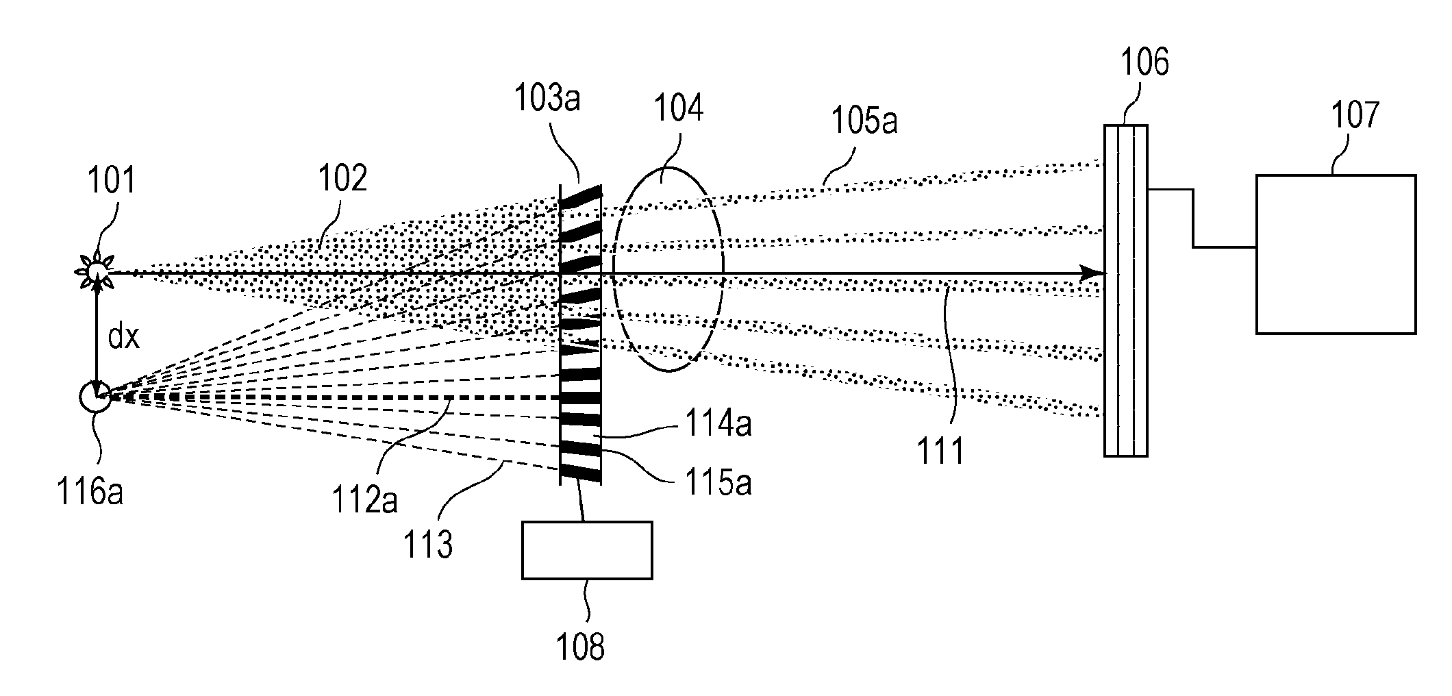
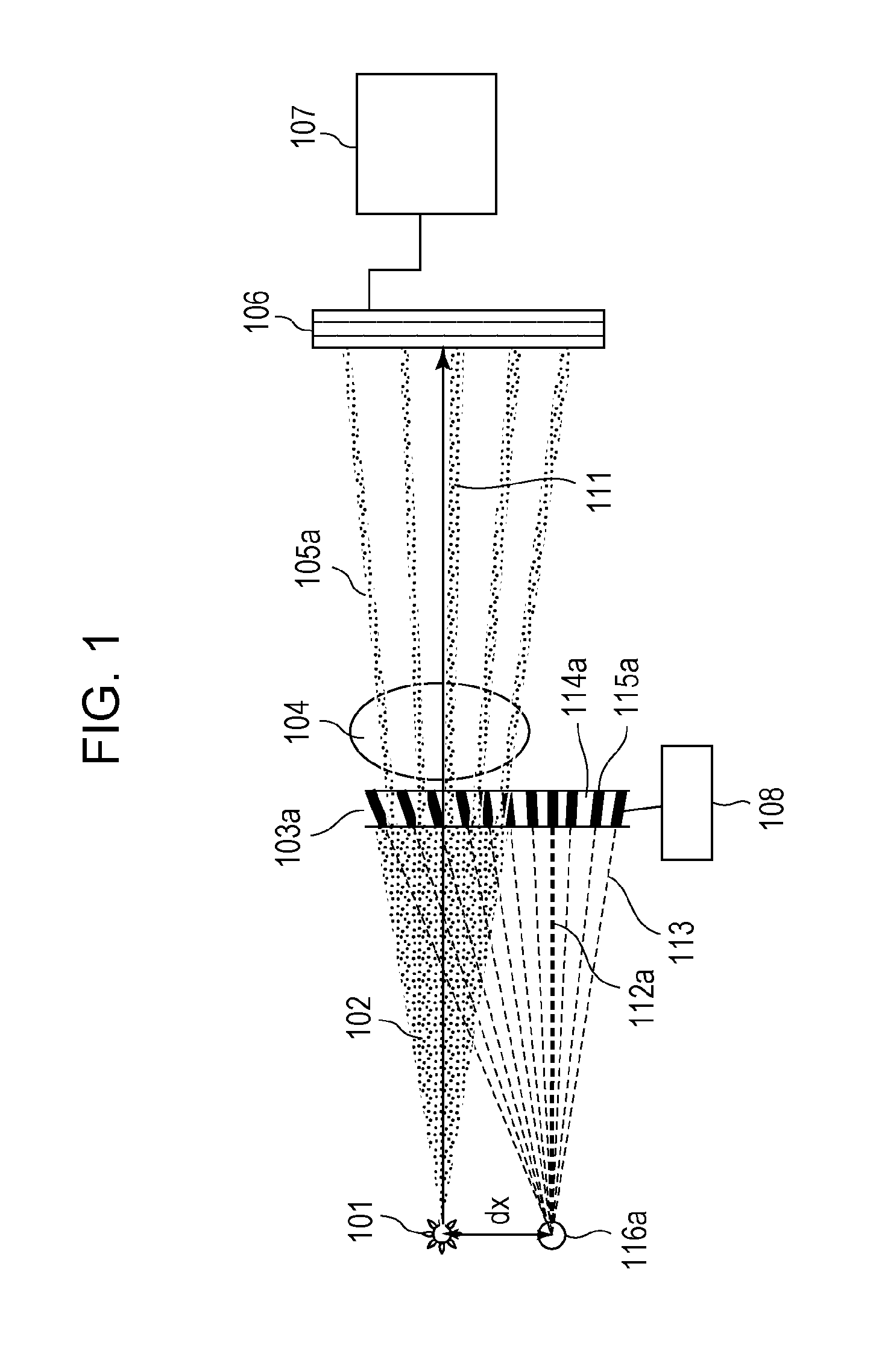
[0032]FIG. 1 shows a schematic diagram of an X-ray imaging apparatus according to a first embodiment.
[0033]The X-ray imaging apparatus shown in FIG. 1 includes an X-ray source 101, a grating 103a which divides cone beam X-rays 102 irradiated from the X-ray source 101 and forms discrete X-ray beams 105a, a detector 106 which detects the discrete X-ray beams 105a, and a calculation device 107 which performs calculation on the basis of a detection result of the detector 106. The X-ray imaging apparatus also includes a moving / rotating unit 108 of the grating 103a. A sample 104 may be placed between the grating 103a and the detector 106 as shown in FIG. 1, or may be placed between the X-ray source 101 and the grating 103a.
[0034]As described above, the X-ray source which generates the cone beam X-rays 102 is used in the X-ray imaging apparatus of the present embodiment. Here, the X-ray source may generate diverging X-rays other than the cone beam X-rays. For example, an X-ray source that...
second embodiment
[0054]FIG. 4 shows a configuration example of an X-ray imaging apparatus according to a second embodiment. The X-ray imaging apparatus of the second embodiment has the same configuration as that of the X-ray imaging apparatus of the first embodiment except for an arrangement of the grating 103a.
[0055]FIG. 5 is an enlarged diagram of a portion from the X-ray source 101 to the grating 103a in FIG. 4 and shows a state in which the cone beam X-rays 102 are divided by the grating 103a and the discrete X-ray beams 105b are formed. The grating 103a is the same as the grating 103a used in the X-ray imaging apparatus of the first embodiment and there is the focused position 116a.
[0056]The arrangement of the grating 103a of the X-ray imaging apparatus of the second embodiment will be described. First, the grating 103a is arranged so that the focused position 116a of the grating corresponds to the arrangement position of the X-ray source 101. Then, the grating 103a is rotated. Although the g...
third embodiment
[0063]FIG. 6 shows a configuration example of an X-ray imaging apparatus according to a third embodiment.
[0064]The X-ray imaging apparatus of the third embodiment has the same configuration as that of the X-ray imaging apparatus of the first embodiment except for a grating 103c and an arrangement of the grating 103c.
[0065]FIG. 7 is an enlarged diagram of a portion from the X-ray source 101 to the grating 103c in FIG. 6 and shows a state in which the cone beam X-rays 102 are divided by the grating 103c and the discrete X-ray beams 105c are formed. As shown in FIG. 7, the grating 103c used in the present embodiment includes opaque objects 115c and transparent objects 114c so that all the incident angles of the cone beam X-rays 102 to the opaque objects 115c are the same angle θ3 when a focused position 116c of the grating and the X-ray source are located at specific positions. In the X-ray imaging apparatus shown in FIG. 7, the incident angles of the cone beam X-rays 102 to the opaqu...
PUM
| Property | Measurement | Unit |
|---|---|---|
| θ | aaaaa | aaaaa |
| θ | aaaaa | aaaaa |
| angle | aaaaa | aaaaa |
Abstract
Description
Claims
Application Information
 - R&D
- Intellectual Property
- Life Sciences
- Materials
- Tech Scout
- Unparalleled Data Quality
- Higher Quality Content
- 60% Fewer Hallucinations
Browse by: Latest US Patents, China's latest patents, Technical Efficacy Thesaurus, Application Domain, Technology Topic, Popular Technical Reports.
© 2025 PatSnap. All rights reserved.Legal|Privacy policy|Modern Slavery Act Transparency Statement|Sitemap|About US| Contact US: help@patsnap.com