
Thermal cycler and control method of thermal cycler

a control method and cycler technology, applied in the field of thermal cycler and a control method of thermal cycler, can solve the problems of inability to accurately perform the subsequent pcr, complex equipment, and time-consuming reaction, and achieve the effect of shortening the time taken for reaction and suppressing the reduction of the reaction accuracy of rt-pcr

Active Publication Date: 2013-10-03
SEIKO EPSON CORP
View PDF9 Cites 5 Cited by
  • Summary
  • Abstract
  • Description
  • Claims
  • Application Information

AI Technical Summary

Benefits of technology

The invention provides a thermal cycler and control method that can improve the accuracy of RT-PCR reactions and reduce reaction time. The cyenser is designed to hold the reaction solution in a specific position, allowing for temperature control without deactivating the enzyme responsible for the reaction. The heating units are controlled to alleviate the effect of gravity on the reaction solution, ensuring uniform heating and improved reaction accuracy. The attachment unit can be switched between two arrangements, allowing for further control of the reaction solution temperature. Overall, the invention provides a more efficient and reliable method for conducting RT-PCR reactions.

Problems solved by technology

However, in the technique of related art, there have been problems that large amounts of reagent etc. are necessary, equipment becomes complex for realization of thermal cycling necessary for reaction, and the reaction takes time.
If the reverse transcriptase enzyme is deactivated and sufficient reverse transcription reaction becomes impossible, it is impossible to accurately perform the subsequent PCR, and the reaction accuracy of RT-PCR may be lower.

Method used


Image

  • Thermal cycler and control method of thermal cycler
  • Thermal cycler and control method of thermal cycler
  • Thermal cycler and control method of thermal cycler

Examples


Embodiment Construction

[0037]As below, preferred embodiments of the invention will be explained in detail using the drawings. Note that the embodiments to be explained do not unduly limit the invention described in the appended claims. Further, not all of the configurations to be explained are essential component elements of the invention.

1. Overall Configuration of Thermal Cycler According to Embodiment

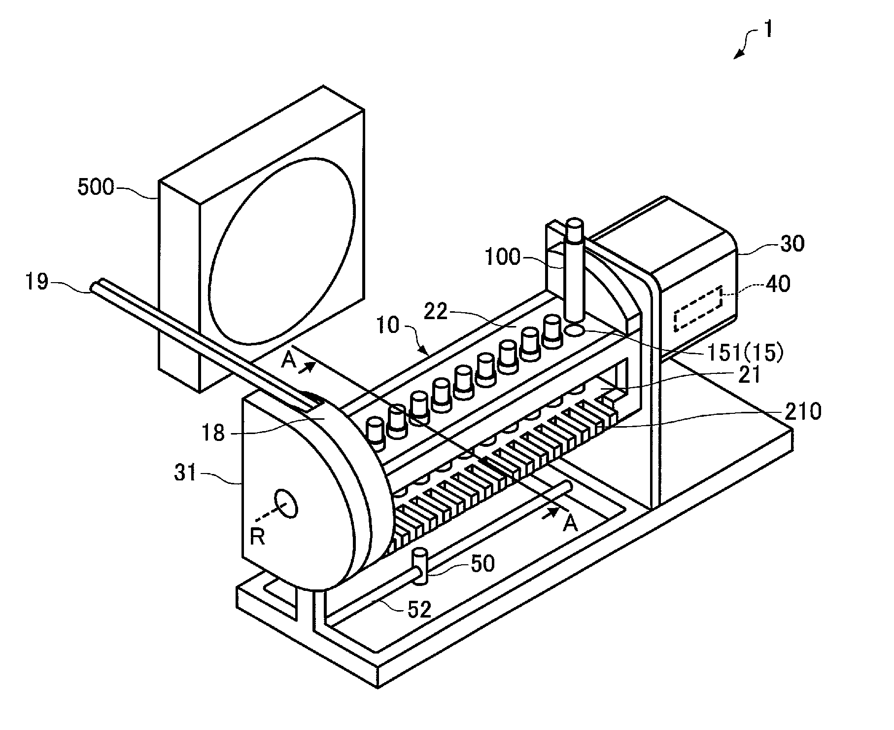
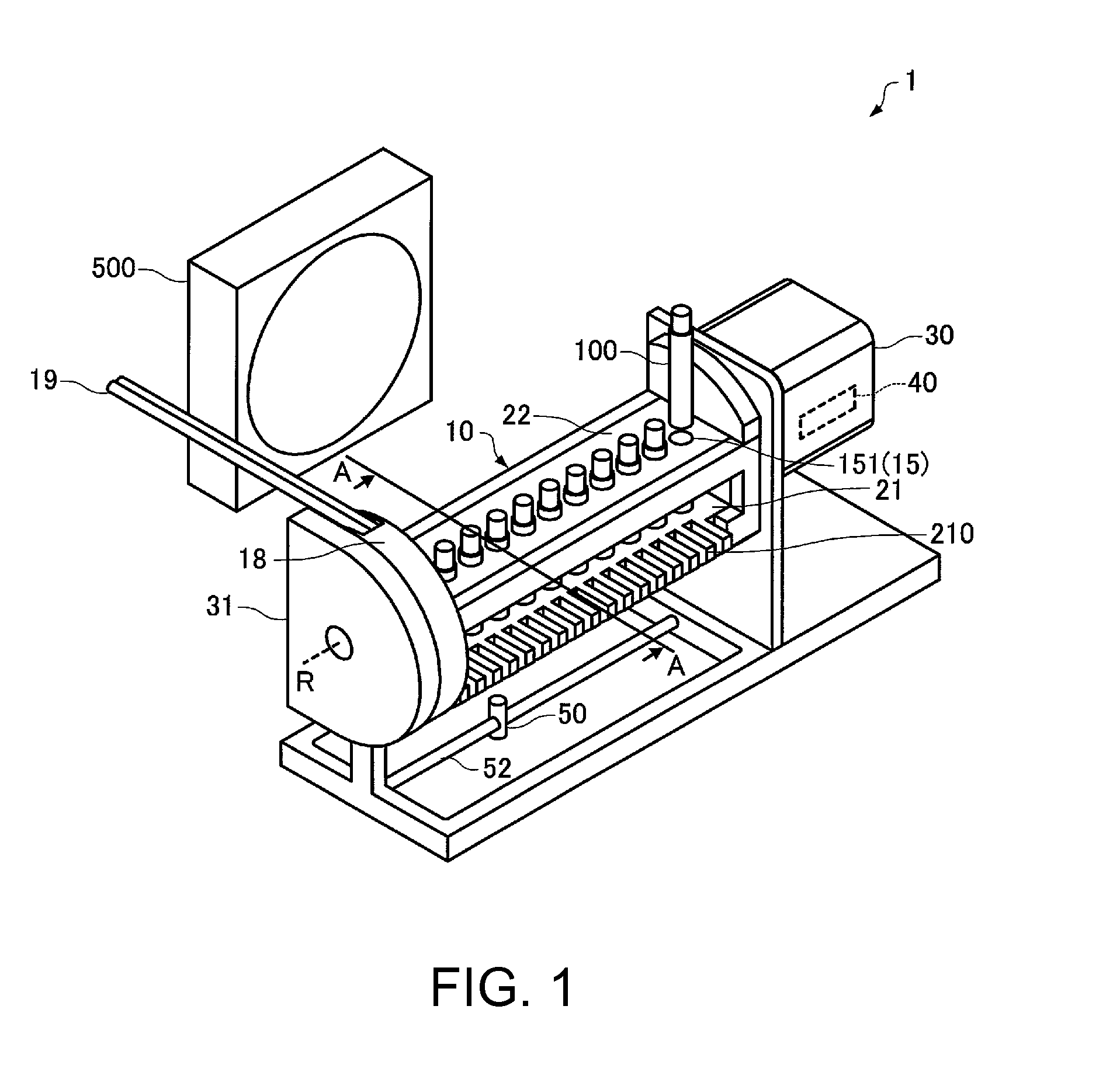
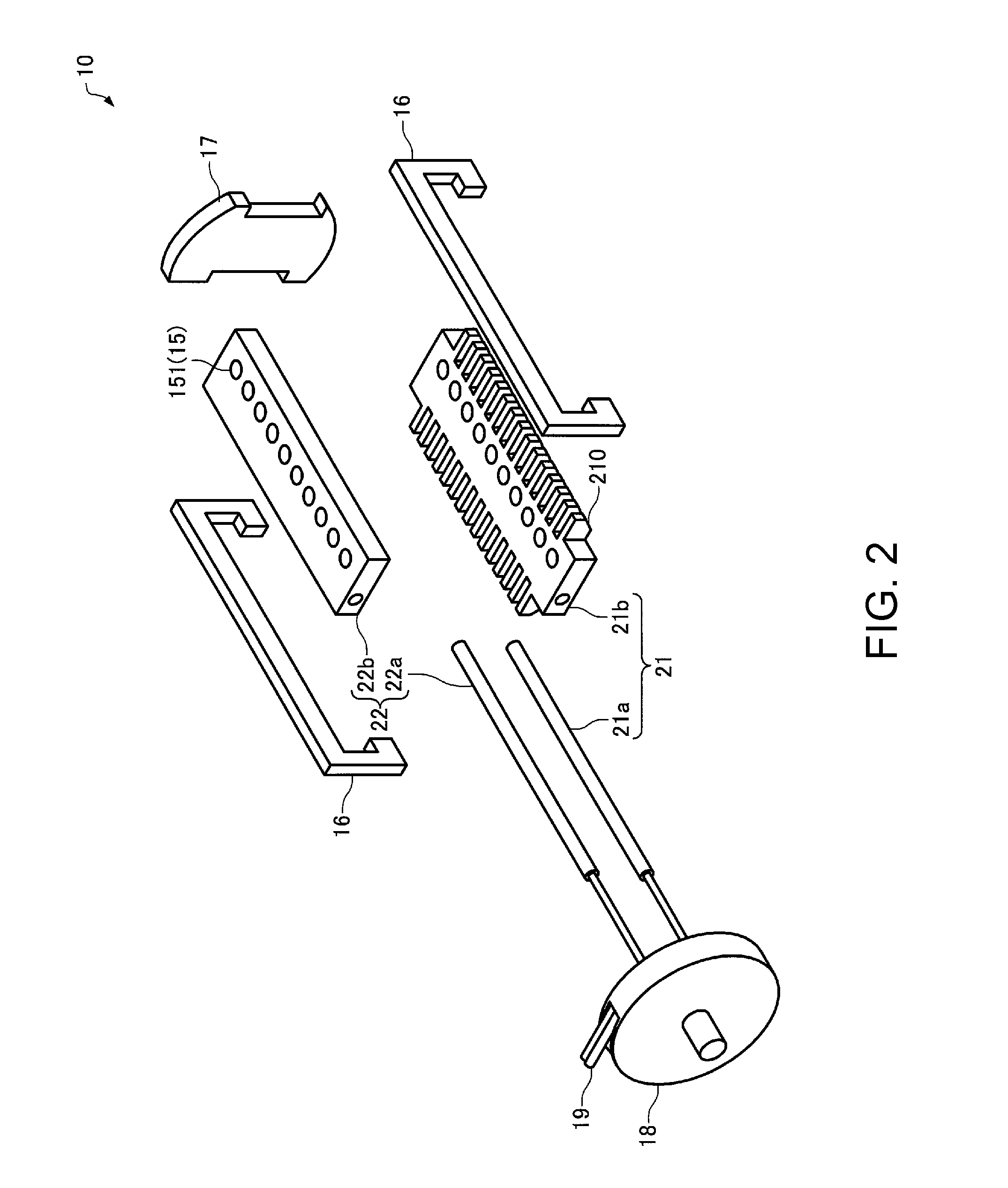
[0038]FIG. 1 is a perspective view of a thermal cycler 1 according to an embodiment. FIG. 2 is an exploded perspective view of a main body 10 of the thermal cycler 1 according to the embodiment. FIG. 3 is a vertical sectional view along A-A line in FIG. 1. In FIG. 3, arrow g indicates a direction in which gravity acts.

[0039]The thermal cycler 1 according to the embodiment includes an attachment unit 15 having an insertion opening 151 for insertion of a reaction container 100 including a channel 110 filled with a reaction solution 140 containing reverse transcriptase enzyme and a liquid 130 having a lower s...


PUM


Abstract

A thermal cycler includes an attachment unit having an insertion opening for insertion of a reaction container including a channel filled with a reaction solution containing reverse transcriptase enzyme and a liquid having a lower specific gravity than that of the reaction solution and being immiscible with the reaction solution, a first heating unit that heats a first region of the channel, a second heating unit that heats a second region of the channel nearer the insertion opening than the first region, a drive mechanism that switches arrangement of the attachment unit, the first heating unit, and the second heating unit between a first arrangement and a second arrangement, and the control unit performs the first heating unit to be a temperature at which reverse transcription reaction progresses and the second heating unit to be a temperature at which the reverse transcriptase enzyme is not deactivated.

Description

BACKGROUND[0001]1. Technical Field[0002]The present invention relates to a thermal cycler and a control method of the thermal cycler.[0003]2. Related Art[0004]Recently, with development of utilization technologies of genes, medical treatment utilizing genes such as gene diagnoses and gene therapies has attracted attention, and many techniques using genes for breed identification and breed improvement have been developed in agriculture and livestock fields. As technologies for utilizing genes, a technology such as a PCR (Polymerase Chain Reaction) method has been widespread. Today, the PCR method is an essential technology in elucidation of information of biological materials.[0005]The PCR method is a technique of amplifying target nucleic acid by applying thermal cycling to a solution containing nucleic acid as a target of amplification (target nucleic acid) and reagent (reaction solution). The thermal cycling is processing of periodically applying two or more steps of temperatures ...

Claims


Application Information

Patent Timeline
IPC IPC(8): B01L7/00
CPCB01L7/525B01L2200/0673B01L7/54B01L2300/1805B01L2400/0457B01L2300/0832B01L3/5082
Inventor YAMAGUCHI, AKEMI
Owner SEIKO EPSON CORP
Learn More