
Power factor correction circuit

a power factor and circuit technology, applied in the field of power electronic technology, can solve the problems of reducing the performance and reliability of the switching power supply, polluting the electric grid or affecting the normal operation of the powered device, so as to reduce the common mode noise

Inactive Publication Date: 2013-10-03
DELTA ELECTRONICS INC
View PDF7 Cites 21 Cited by
  • Summary
  • Abstract
  • Description
  • Claims
  • Application Information

AI Technical Summary

Benefits of technology

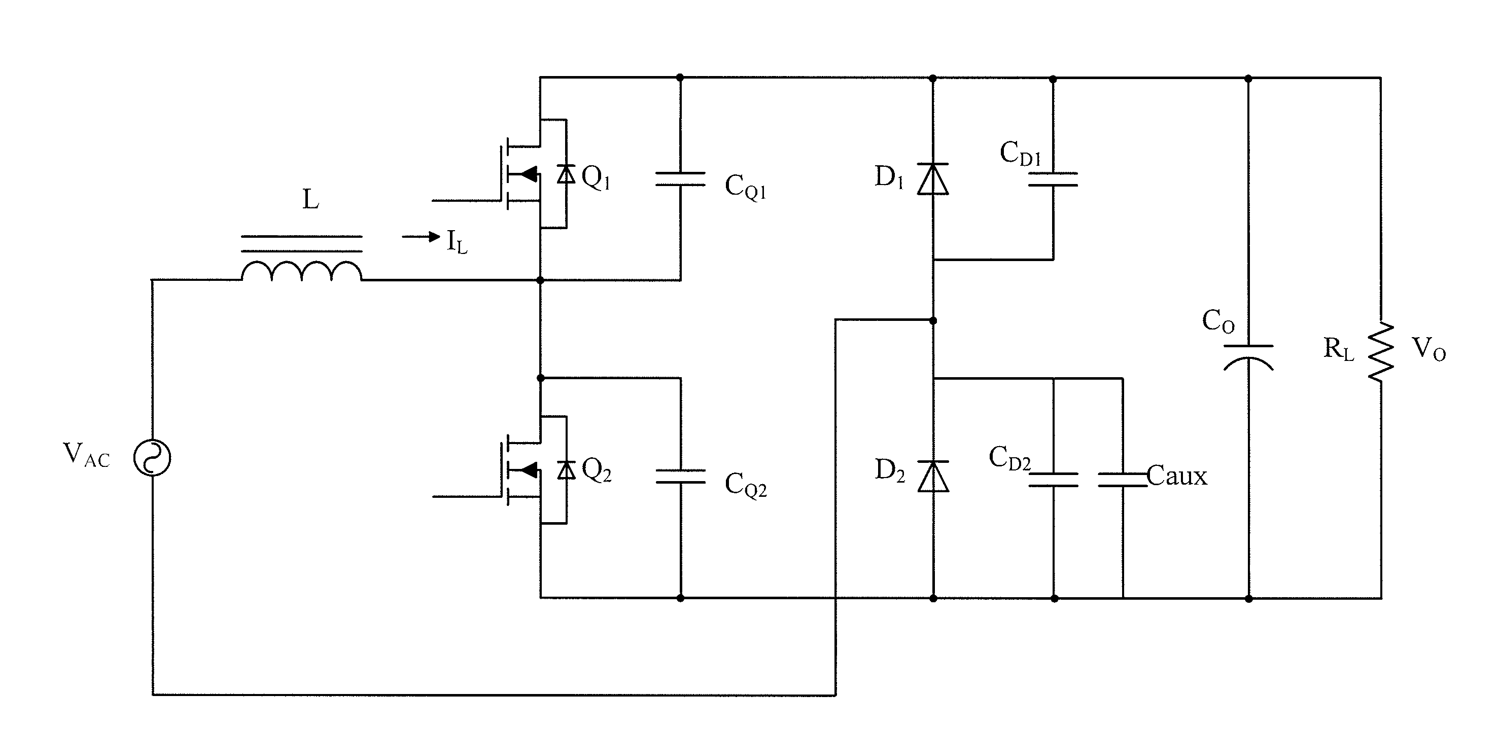
The present patent forms a new power factor correction circuit that can reduce common mode noise and improve circuit reliability and stability. It achieves this by using an auxiliary capacitor that changes the parameters of the resonant network and reduces the resonant frequency of high frequency. Additionally, two surge diodes are used for surge protection of the switch in the circuit. These improvements enhance the effectiveness and stability of power factor correction.

Problems solved by technology

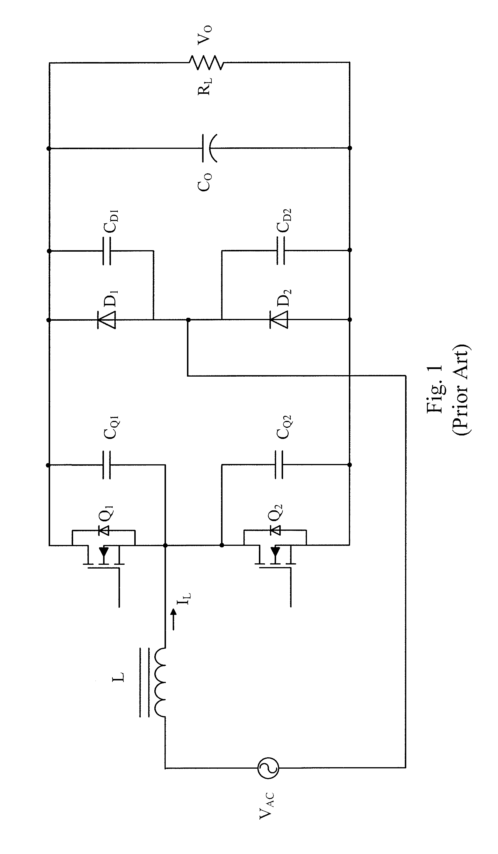
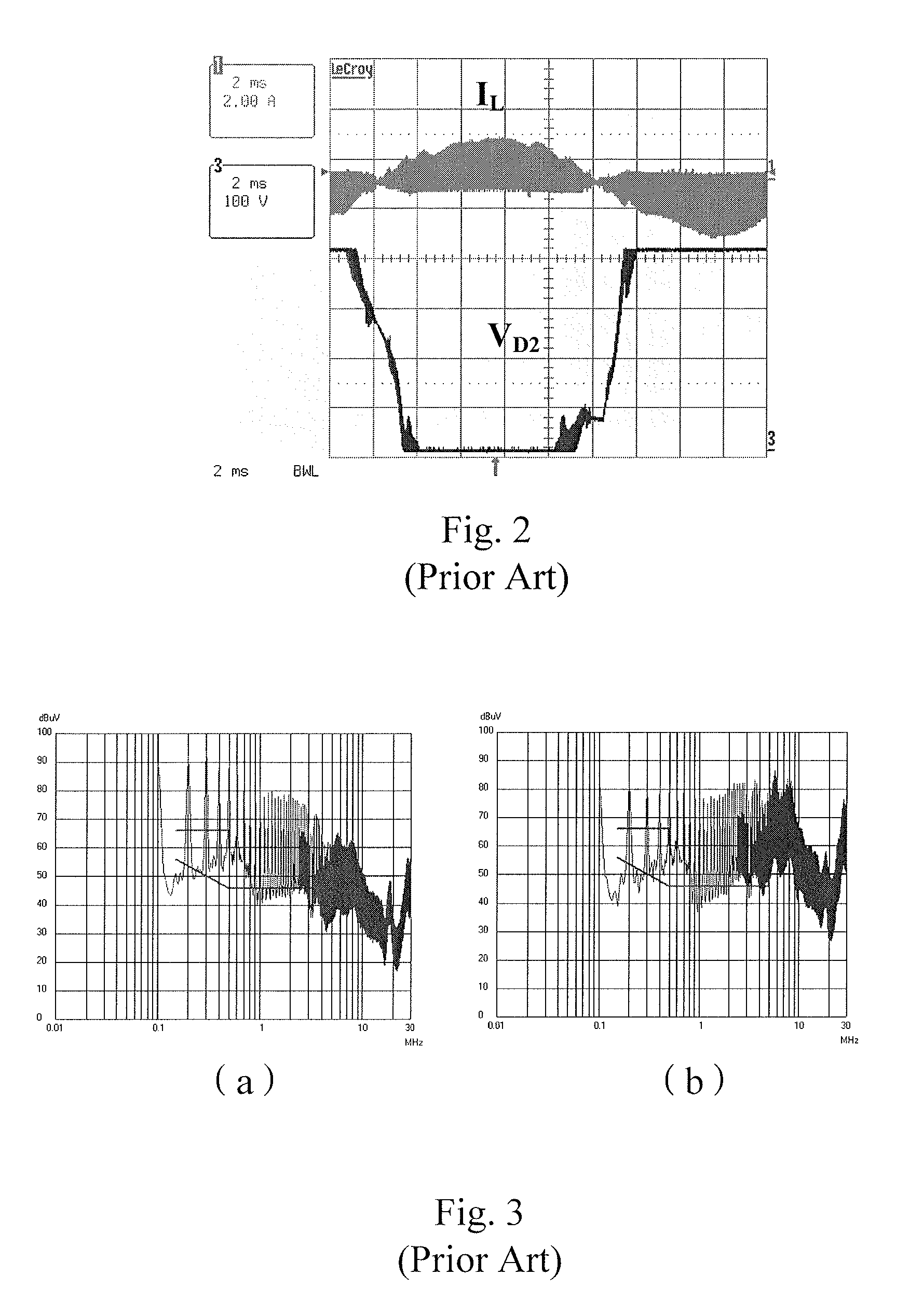
Such harmonic voltage and harmonic current are outputted via a power input line or output line of the switching power supply, which causes pollution of the electric grid or interferes with the normal operation of powered devices.
Furthermore, the harmonic voltage and harmonic current may also interfere with other devices via space radiation, thereby influencing the normal operation of the devices.
More alarmingly, the harmonic voltage and harmonic current cause electromagnetic interference in the switching power supply, so that the components in the switching power supply cannot operate stably, ultimately resulting in the performance and reliability of the switching power supply being reduced.
Thus high-frequency jumping voltage and significant common mode noise are caused, which reduces the reliability of the PFC converter.
However, an appropriate solution has yet to be developed.

Method used


Image

  • Power factor correction circuit
  • Power factor correction circuit
  • Power factor correction circuit

Examples


Embodiment Construction

[0037]In order to make the technical contents of the present disclosure more detailed and comprehensive, various embodiments of the present disclosure are described below with reference to the accompanying drawings. Wherever possible, the same reference numbers are used in the drawings and the description to refer to the same or like parts. However, those of ordinary skill in the art should understand that the embodiments described below are not used for limiting the scope of the present disclosure. Moreover, the accompanying drawings are only used for illustration and are not drawn to scale.

[0038]In the embodiments and the claims of the present disclosure, the description is relating to “coupled with” may refer to an arrangement in which a component is indirectly connected to another component through other components, and may also refer to an arrangement in which a component is directly connected to another component without using other components.

[0039]In the embodiments and the ...


PUM


Abstract

The present disclosure provides a power factor correction circuit. The power factor correction circuit includes an AC power, a first bridge arm, a second bridge arm and at least one auxiliary capacitor. The AC power has first and second ends. The first bridge arm includes first and second switches connected in series with each other. A second terminal of the first switch is connected to a first terminal of the second switch, and is coupled to the first end of the AC power via a first inductor. The second bridge arm is connected in parallel with the first bridge arm, and includes third and fourth switches connected in series with each other. A second terminal of the third switch is connected to a first terminal of the fourth switch and the second end of the AC power. The auxiliary capacitor is connected to the third or fourth switch in parallel.

Description

RELATED APPLICATIONS[0001]This application claims priority to Chinese Application Serial Number 201210092652.3, filed Mar. 29, 2012, which is herein incorporated by reference.BACKGROUND[0002]1. Field of Invention[0003]The present disclosure relates to the field of power electronic technology. More particularly, the present disclosure relates to a power factor correction circuit (PFC) capable of reducing common-mode noise and EMI intensity.[0004]2. Description of Related Art[0005]The semiconductor and magnetic component of a switching power supply operate at a high-frequency switching state, so that very high di / dt and dv / dt are caused and thus significant harmonic voltage and harmonic current are generated. Such harmonic voltage and harmonic current are outputted via a power input line or output line of the switching power supply, which causes pollution of the electric grid or interferes with the normal operation of powered devices. Furthermore, the harmonic voltage and harmonic cur...

Claims


Application Information

Patent Timeline
Patent Type & Authority Applications(United States)
IPC IPC(8): G05F1/70
CPCH02M1/4233H02M1/4266H02M2003/1586H02M2001/0064Y02B70/123Y02B70/10Y02P80/10H02M1/0064H02M3/1586H02M1/0085
Inventor YAN, CHAOTIAN, RUI-FEI
Owner DELTA ELECTRONICS INC
Learn More