
Methods and devices for restoring control and resuming production at an offshore oil well following an uncontrolled fluid release after an explosion

a technology of oil well and fluid release, which is applied in the direction of drilling pipes, drilling/well accessories, sealing/packing, etc., can solve the problems of uncontrolled fountain, human casualties, environmental pollution, etc., and achieve the effect of fluid releas

Inactive Publication Date: 2013-10-03
TSEYTLIN SIMON +1
View PDF4 Cites 1 Cited by
  • Summary
  • Abstract
  • Description
  • Claims
  • Application Information

AI Technical Summary

Benefits of technology

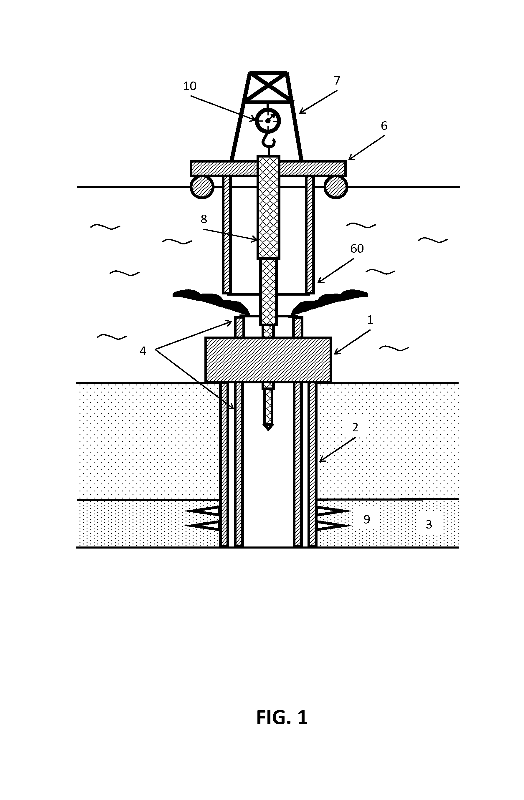
This patent is about improving methods and devices for controlling oil wells after explosions or blowouts. The invention provides methods for quickly restoring control over the damaged oil well and adjusting flow production for the remaining lifespan of the well. This will help to prevent uncontrolled release of fluids into the environment and minimize fluid release from the oil well. The invention also provides for sealing off the oil well or resuming oil production, depending on the circumstances. Overall, the invention offers a quick, efficient, and less expensive way to regain control over oil wells after damage.

Problems solved by technology

This may cause a gas explosion that may result in human casualties, environmental pollution and the creation of an uncontrolled fountain.
This uncontrolled fountain is very difficult to suppress, because the wellhead is under enormous pressure.
As offshore drilling on the continental shelves is progressing into deeper and deeper waters, the problem is many times more complicated when the explosion occurs in deep waters.
Suppressing such a well and cleaning of the environment may cost billions of dollars.
This method has proved to be the most rapid, but it can currently only be used in the case of well blowouts in shallow water, i.e. less than 1,000 meters deep.
Inserting such a large string of pipes presents a challenge due to an enormous pressure in the well urging the killing string out of the well.
This method takes a long time (several months) while allowing for the uncontrolled release to continue polluting the waters with large quantity of oil.
This process is also quite expensive.
In addition, there is always an uncertainty present as to the exact location of the well deep down under the sea bottom.
To date, no practical equipment or method is available to the industry for the purpose of regaining control of a deep water abandoned wellhead on the offshore seabed after a blowout causing spilling of reservoir fluids into the sea.
The environmental pollution caused by such outpouring of reservoir fluids and gases can have disastrous consequences, as evident by the 2011 pollution created over a large section of the Gulf of Mexico and adjacent beaches by the erupted BP well off the coast of Mexico.

Method used


Image

  • Methods and devices for restoring control and resuming production at an offshore oil well following an uncontrolled fluid release after an explosion
  • Methods and devices for restoring control and resuming production at an offshore oil well following an uncontrolled fluid release after an explosion
  • Methods and devices for restoring control and resuming production at an offshore oil well following an uncontrolled fluid release after an explosion

Examples


first embodiment

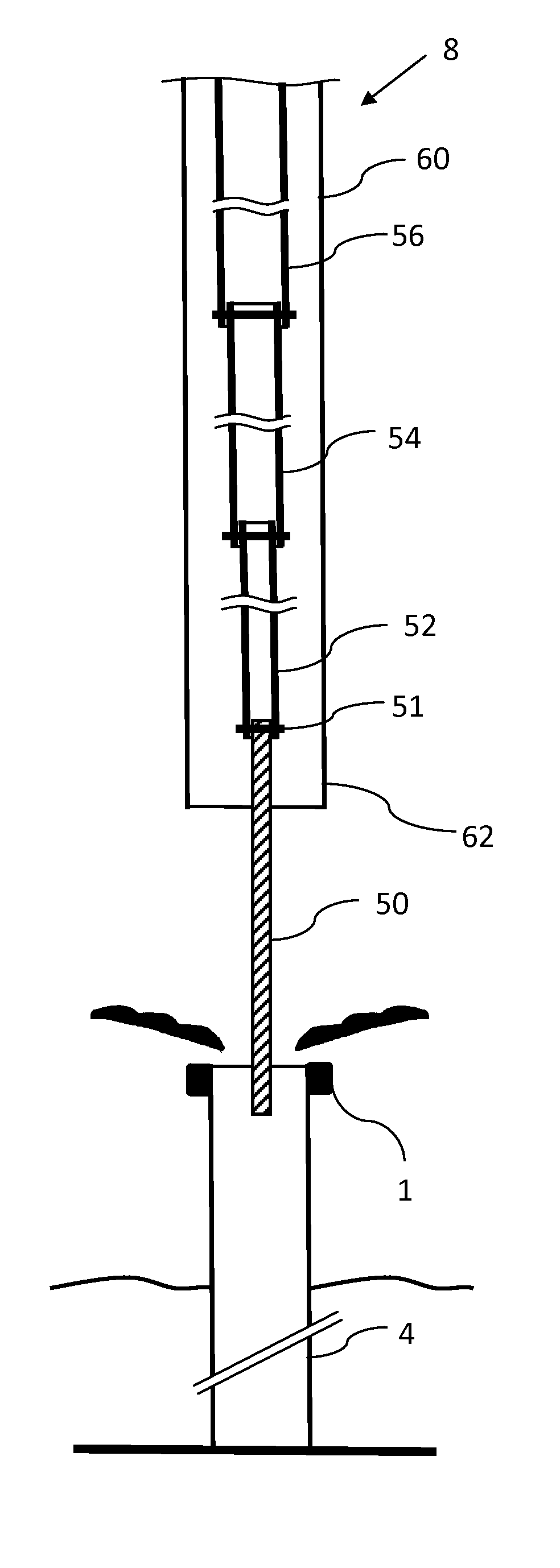
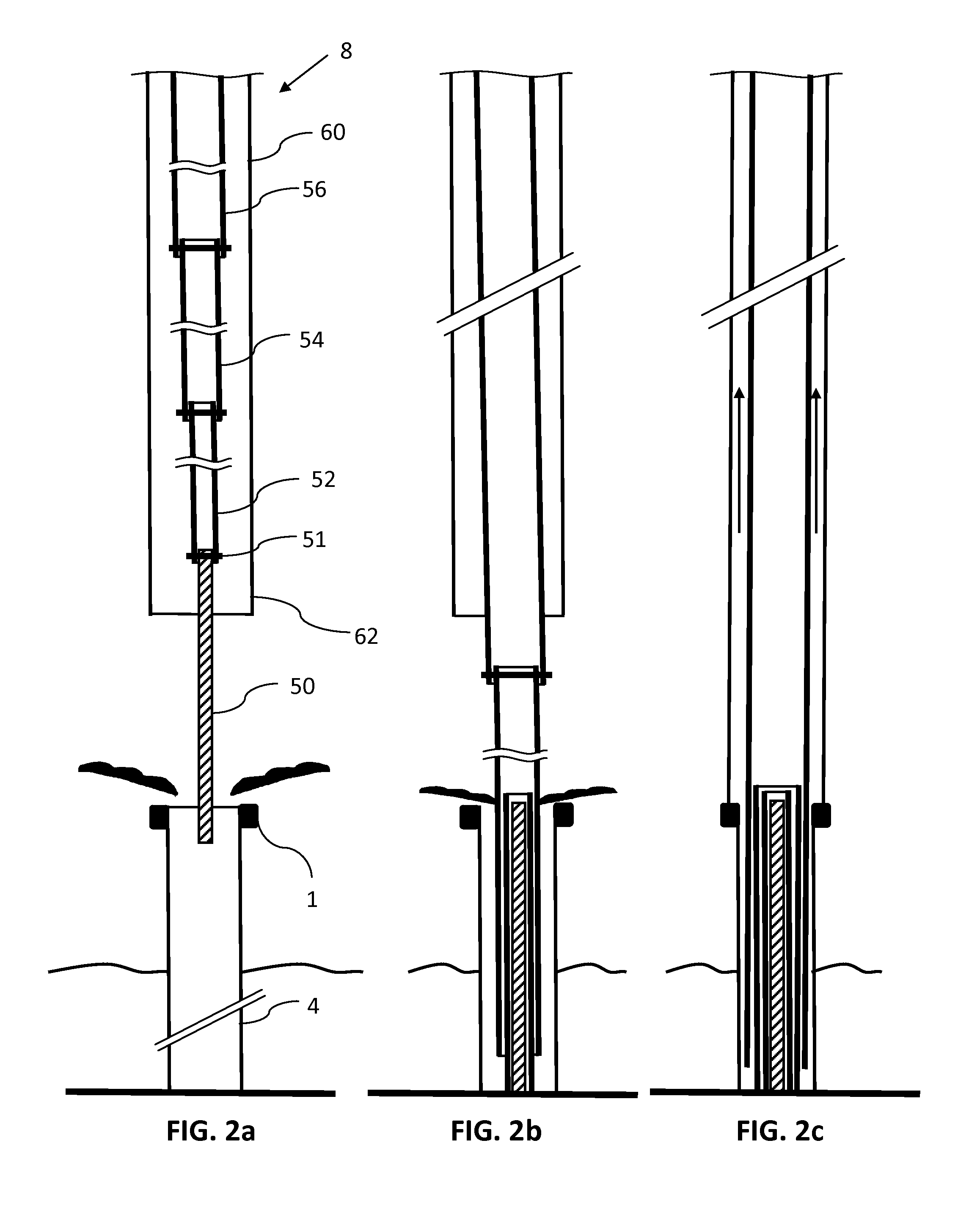
[0052]FIGS. 2a through 2d illustrate an example of the method of the invention according to the Shown in FIG. 2a is the beginning of the process of lowering the flow restricting assembly 8 into the well pipe 4 through the lower end 62 of the riser 60 positioned above and aligned with the BOP 1. The flow restricting assembly 8 in this case consists of the first solid insert 50 attached to a higher insert pipe 52, which in turn is attached to a higher and larger insert pipe 54 and finally the assembly 8 includes the upper insert pipe 56. Each successive pipe 52, 54, and 56 may be made to accept the adjacent lower insert inside thereof. The attachments 51 between successive flow restricting inserts may be made to allow hanging of the lower insert at the end of the higher insert respectively. One example of such attachment is shown in FIGS. 4a and 4b, while another example is shown in FIGS. 5a and 5b which are discussed in more detail below.

[0053]Upon reaching the bottom of the well, t...

second embodiment

[0057]FIGS. 3a and 3b show another disposition of the oil well according to the invention, in which individual flow restricting inserts are configured to be engaged and attached to each other allowing the entire assembly to collapse or extend axially like a “spy glass”. One such engagement design between adjacent inserts of the flow restricting assembly is shown in FIGS. 5a and 5b, where each respective portion of flow restricting inserts 50 and 52 has a flange 55 and 59. The flanges 55 and 59 may be configured to overlap each other such that during lowering of the flow restricting assembly 8 into the oil well pipe 4, the lower insert is supported by the adjacent higher insert (as seen in FIG. 5a). Upon reaching the bottom of the well, the lower insert 50 may stop and disengage from the next insert 52, which can continue its descent, shown with arrows in FIG. 5b. Other possible designs of the ends of respective inserts 50 and 52 may include a bayonet-type design or other fittings th...

third embodiment

[0062]FIG. 7 illustrates the method of the invention in which a central portion of the flow restricting assembly 8 is made as a telescopic permanent assembly of solid rods of increasing diameters 50, 52, and 54, while the outer portion is made using one or more sliding flow restricting rods 56. In embodiments, once the control over the oil well is regained, the central telescopic rod assembly may be lifted to adjust the flow of oil from the well or removed entirely so that oil production may proceed through the outer insert 56.


PUM


Abstract

Methods and devices for restoring control of at an offshore oil well following an uncontrolled fluid release after an explosion include lowering through a riser of successive flow restricting inserts into the oil well to gradually reduce the uncontrolled fluid release. Flow restricting inserts may be inserted in parallel or in series with each other. Following attachment of the riser to the oil well, provisions are made to restore oil production from the well. Flow restricting inserts may further be used to adjust flow resistance from the well in order to optimize oil production. Passages between the riser and the flow restricting inserts may also be used to form a gas lift in order to maximize production of oil from the well.

Description

CROSS-REFERENCE DATA[0001]This application is a continuation-in-part of the co-pending U.S. patent application Ser. No. 13 / 675,975 filed 13 Nov. 2012 entitled “Method and Alignment System for Killing an Uncontrolled Oil-Gas Fountain at an Offshore Oil Platform Using a Telescopic Insert Assembly”; which in turn claims the priority date benefit from a U.S. Provisional Application No. 61 / 681,257 filed 9 Aug. 2012 and entitled “The Method of Killing an Uncontrolled Oil-Gas Fountain at an Offshore Oil Platform Using a Telescopic Insert Assembly”.[0002]This application is also a continuation-in-part of the co-pending U.S. patent application Ser. No. 13 / 184,497 filed 16 Jul. 2011, now U.S. Pat. No. 8,448,709 entitled “Method of Killing an Uncontrolled Oil-Gas Fountain Appeared After an Explosion of an Offshore Oil Platform”; which in turn claims a priority benefit of the U.S. Provisional Patent Application No. 61 / 367,478 filed 26 Jul. 2010.[0003]All cited above patent documents are incorpo...

Claims


Application Information

Patent Timeline
Patent Type & Authority Applications(United States)
IPC IPC(8): E21B43/01
CPCE21B17/01E21B43/0122E21B7/12E21B34/04E21B29/12
Inventor TSEYTLIN, SIMONTSEYTLIN, DAVID
Owner TSEYTLIN SIMON
Learn More