
Air swimming toy with driving device

a driving device and air-swimming toy technology, which is applied in aquatic toys, toys, aquatic toys, etc., can solve the problems of track member detachment from the toy body, track member cannot be secured to the bottom side of the toy body, and the direction of the air-swimming toy is difficult to be controlled by conventional air-swimming toys, etc., to achieve the aesthetic appearance of the air-swimming toy, minimizing noise noise reduction

Inactive Publication Date: 2013-09-26
CHENG RANDY
View PDF23 Cites 3 Cited by
  • Summary
  • Abstract
  • Description
  • Claims
  • Application Information

AI Technical Summary

Benefits of technology

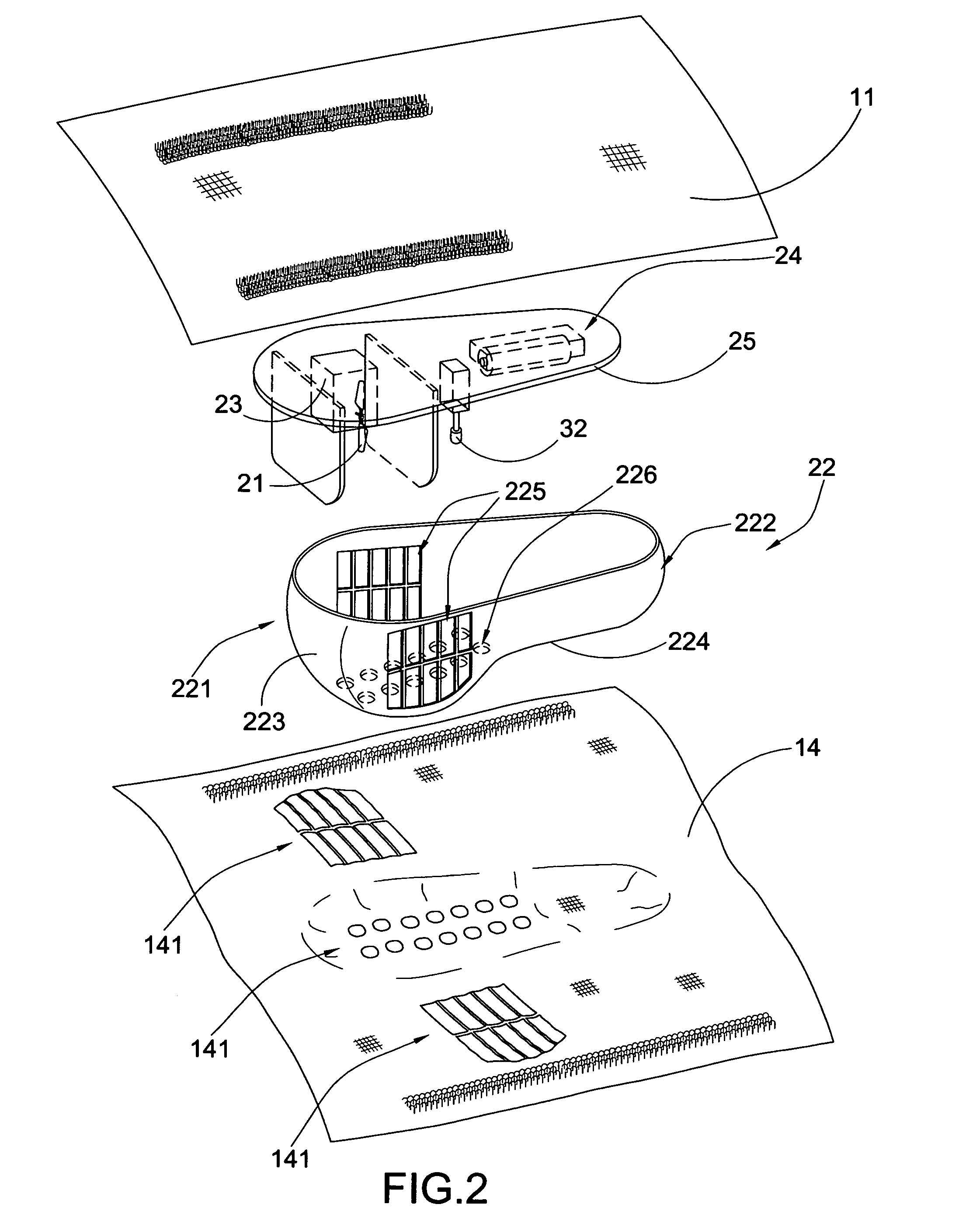
The invention is an air swimming toy that has the advantage of being controlled by an air pressure difference created underneath the toy body. This difference is created by a driving device that uses an air propeller to push air under the toy body. The driving device is fixed at the bottom side of the toy body to prevent accidental detachment. Additionally, the driving device is small in size to keep the toy's appearance attractive. The only part of the toy that is driven is the air propeller, which minimizes noise during operation.

Problems solved by technology

However, the conventional air-floating toy is hard to be controlled its direction and elevation.
However, the driving mechanism has several drawbacks.
However, the track member cannot be secured to the bottom side of the toy body.
In addition, the weight of weight member keeps shifting between the front and rear ends of the track member, such that the sliding movement and the weight shifting force will cause the track member detaching from the toy body.
In worst case, if one of the front and rear ends of the track member is detached from the bottom side of the toy body, the weight member will not able to slide at the track member to control the altitude of the air-floating toy.
However, the actuation of the gear wheel requires relatively higher electrical power such that the weight member will run out of battery rapidly.
An unavoidable noise will be generated during the actuation of the gear wheel.
The driving mechanism requires relatively larger installation space at the bottom side of the toy body.
In other words, the size of the driving mechanism cannot be minimized and the driving mechanism will destroy the aesthetic appearance of the toy body especially when the toy body floats in the air.

Method used


Image

  • Air swimming toy with driving device
  • Air swimming toy with driving device
  • Air swimming toy with driving device

Examples


Embodiment Construction

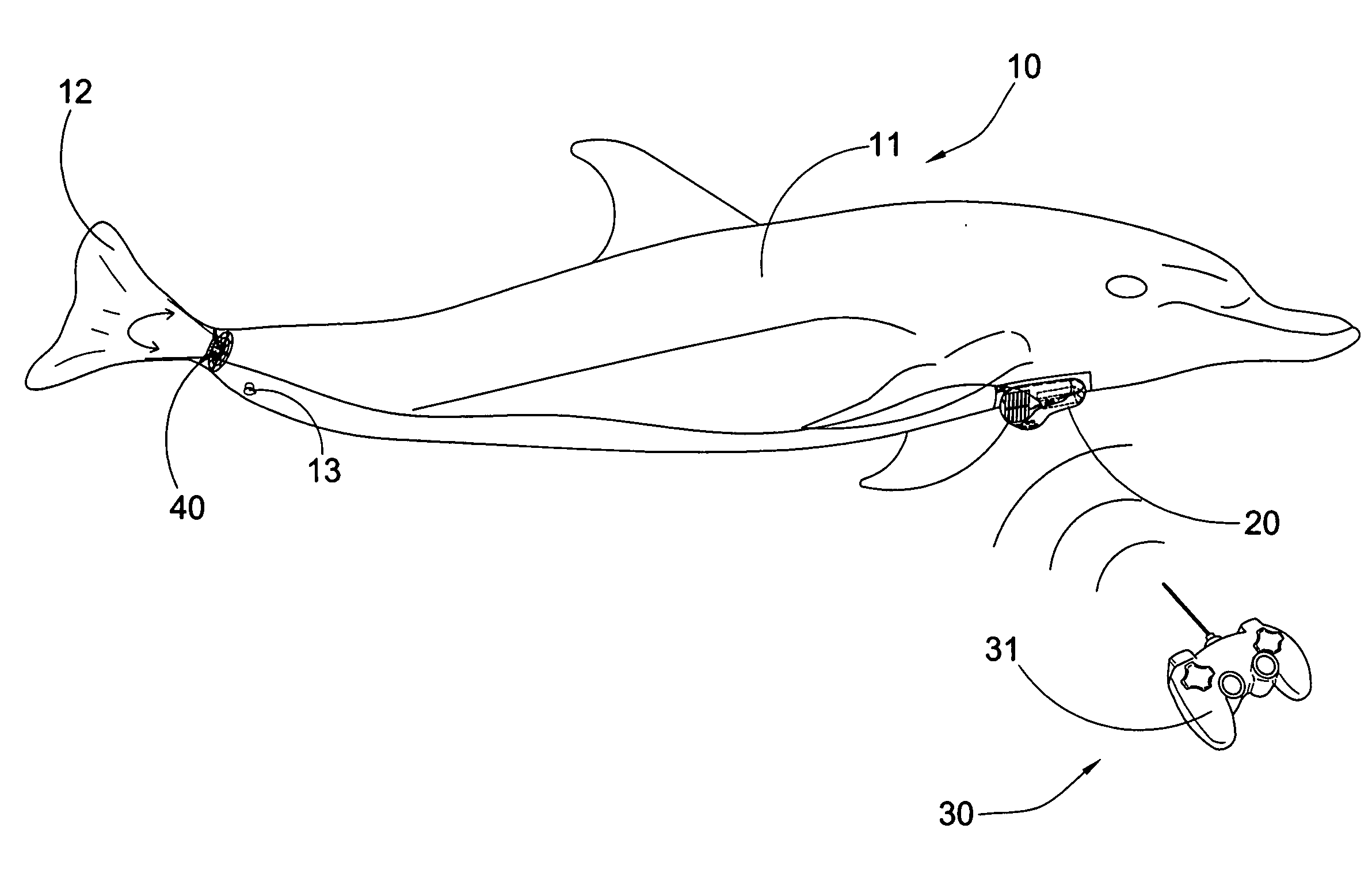
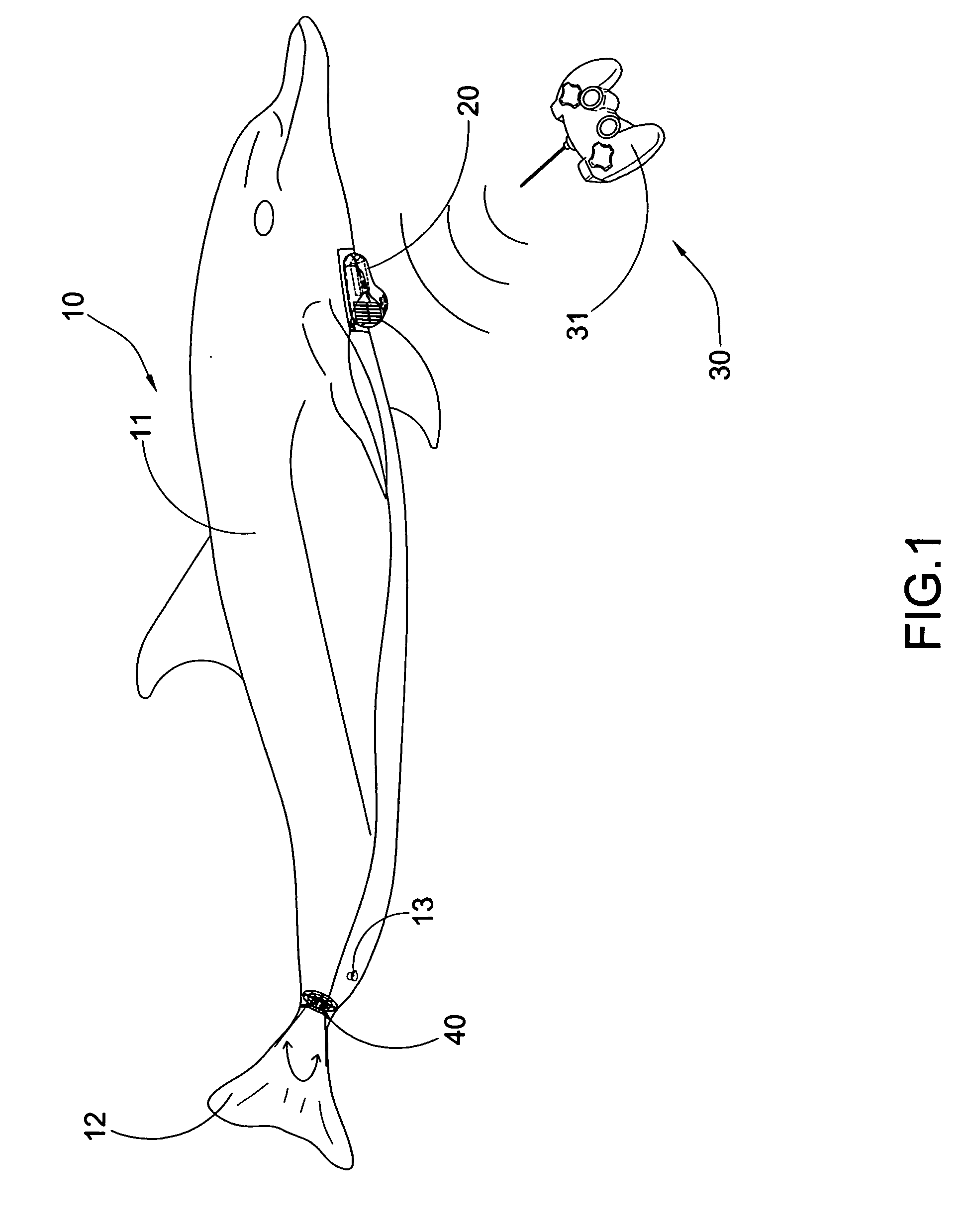
[0031]Referring to FIGS. 1 to 3 of the drawings, an air swimming toy according to a preferred embodiment of the present invention is illustrated, wherein the air swimming toy comprises a toy body 10, a driving device 20, and a remote controller 30.

[0032]The toy body 10 comprises a floating body 11 and a tail body 12 movably coupled with the floating body 11, wherein the floating body 11 is filled with a particular gas, such as helium, in order to float in the air. In particular, the toy body 10 further comprises a valve 13 provided at the floating body 11 for filling the gas thereinto. The floating body 11 is made of high quality, durable nylon material that will stay inflated for a relatively long period of time, such as a week. The gas can be refilled to the floating body 11 via the valve 13 to inflate the floating body 11.

[0033]Accordingly, when the tail body 12 is moved in a wiggling motion, the toy body 10 will move forward slowly and smoothly as the swimming motion in the air....


PUM


Abstract

An air swimming toy includes a toy body, a driving device including an air propeller supported at a bottom side of the toy body for creating an air dynamic underneath the toy body, and a remote controller remotely controlling the driving device to operate the air propeller, wherein the air propeller is activated to rotate in order to control an altitude of the toy body via the air dynamic. In particular, when a controllable air pressure underneath the toy body is lesser than a surrounding air pressure, the toy body is elevated in the air, and when the controllable air pressure is higher than the surrounding air pressure, the toy body is dropped down in the air.

Description

BACKGROUND OF THE PRESENT INVENTION[0001]1. Field of Invention[0002]The present invention relates to a remote controlled flying toy, and more particular to an air swimming toy, wherein a driving device of the air swimming toy is arranged for creating an air pressure difference underneath the toy body to control the altitude of the air swimming toy.[0003]2. Description of Related Arts[0004]A plurality of air-floating toys are known which are capable of self-floating in the air and propelling in the air via a remote control. In particular, the air-floating toys are driven by means of a wiggling motion. However, the conventional air-floating toy is hard to be controlled its direction and elevation. An improved air-floating toy generally comprises a toy body, a driving mechanism and a steering mechanism to control the altitude and the direction of the air-floating toy respectively via a remote controller.[0005]The driving mechanism is affixed underneath the toy body to control the altit...

Claims


Application Information

Patent Timeline
IPC IPC(8): A63H23/10
CPCA63H27/10A63H2027/1066A63H30/04
Inventor CHENG, RANDY
Owner CHENG RANDY
Learn More