
Method and Apparatus for Control Plane CPU Overload Protection

a technology of control plane and control plane, applied in the field of communication networks, can solve the problems of cpu core limited or fixed resource capacity, drop of legitimate control packets, denial of service to legitimate control packets, etc., and achieve the effect of increasing the amount of control traffi

Active Publication Date: 2013-09-26
EXTREME NETWORKS INC
View PDF7 Cites 17 Cited by
  • Summary
  • Abstract
  • Description
  • Claims
  • Application Information

AI Technical Summary

Benefits of technology

The patent describes a method and device for controlling the traffic in a network to prevent the control plane from becoming overwhelmed with traffic. It does this by using dynamic meters to classify and limit the traffic that is sent through the network. This helps to ensure that the network can handle the expected traffic levels based on the number of ports and services being used. The system also monitors the usage of the network and adjusts the meters accordingly to maintain optimal performance. Overall, the system provides effective protection against control traffic bursts and ensures that the network can handle heavy usage without slowing down.

Problems solved by technology

A given CPU core has a limited or fixed resource capacity, due to its operating clock frequency and size of memory.
Although this technique can prevent overloading of the CPU core, it suffers from denial of service to legitimate control packets in the presence of traffic anomalies due to loops and malicious attacks.
Use of statically configured filter rules will limit the number of control packets that are passed to the control plane, potentially causing legitimate control packets to be dropped before they are able to be processed by the control plane.
This results in a situation where the network element is not able to be controlled, since control packets are not reaching the control software.
Further, this lack of control unfortunately coincides with a situation where control of the network element is imperative to enable the routing loop to be corrected or to enable the denial of service attack to be quashed.
The problem with this approach is that it does not dynamically adapt to changes in the control plane system configurations.

Method used


Image

  • Method and Apparatus for Control Plane CPU Overload Protection
  • Method and Apparatus for Control Plane CPU Overload Protection
  • Method and Apparatus for Control Plane CPU Overload Protection

Examples


Embodiment Construction

[0018]The following detailed description sets forth numerous specific details to provide a thorough understanding of the invention. However, those skilled in the art will appreciate that the invention may be practiced without these specific details. In other instances, well-known methods, procedures, components, protocols, algorithms, and circuits have not been described in detail so as not to obscure the invention.

[0019]FIG. 1 illustrates one embodiment of a communication network 10. As shown in FIG. 1, users 12 connect to edge network elements 14 to obtain communication services from the network, such as to communicate with other users or obtain access to data and applications available on the network. Core network elements 16 interconnect the edge network elements to enable data to be transmitted throughout the network. Many network configurations have been developed and the functional block diagram shown in FIG. 1 is merely intended to provide context for understanding embodimen...


PUM


Abstract

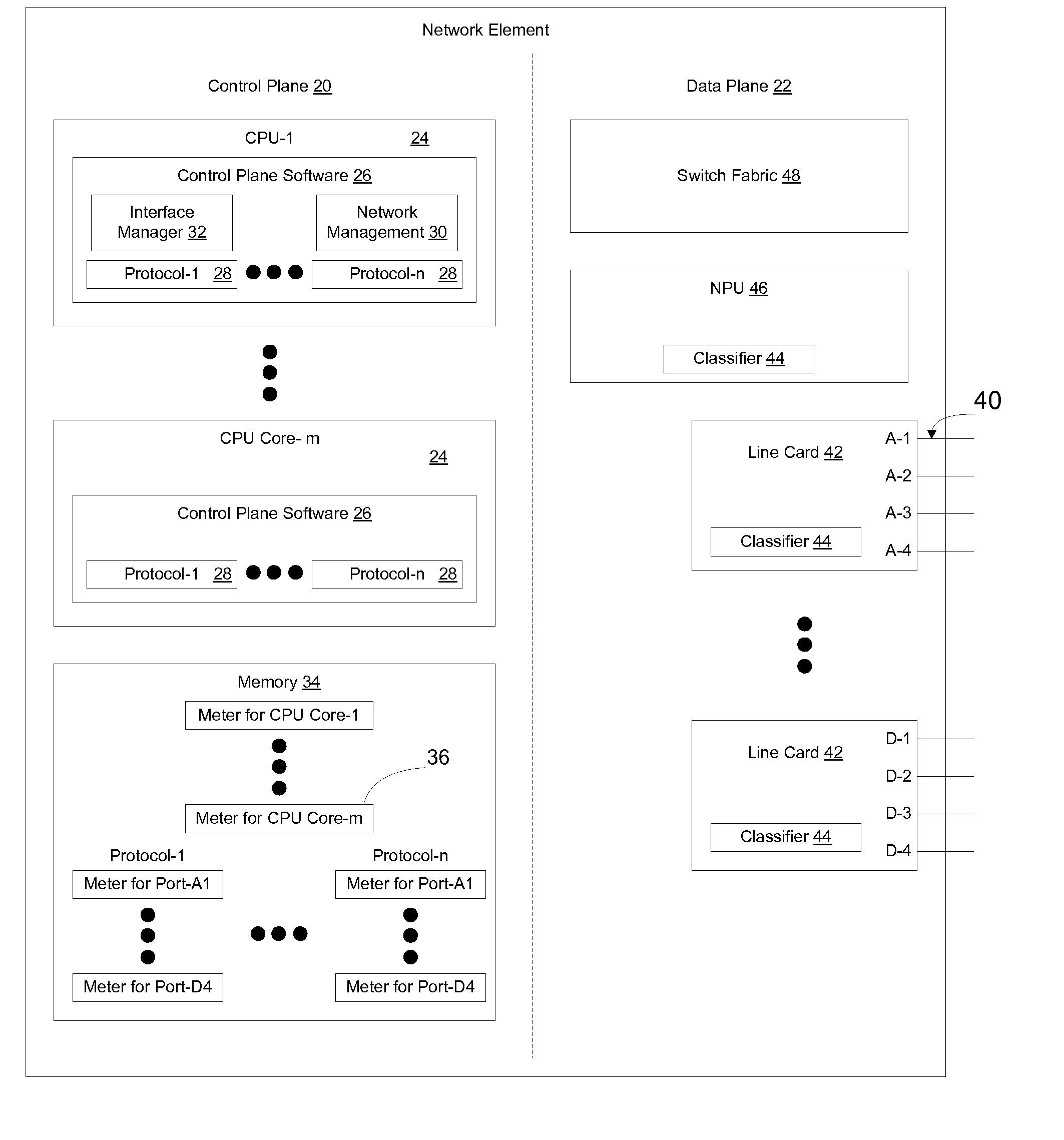
Control packets received at a network element are pre-classified to enable out of profile traffic to be traced to an offending port. Pre-classified control packets are metered at a desired granularity using dynamically configured meters which adjust as ports are put into service or removed from service, and as services are applied to ports. CPU metering is implemented on a per-CPU core basis, but the per-CPU meters are used to perform flow control rather than as thresholds for ejecting errant control traffic. The combination of these three aspects provides robust CPU overload protection while allowing appropriate levels of control traffic to be provided to the control plane for processing, even in the event of a control traffic burst on one or more ports of the network element.

Description

CROSS-REFERENCE TO RELATED APPLICATIONS[0001]None.BACKGROUND[0002]1. Field[0003]This application relates to communication networks and, more particularly, to a method and apparatus for control plane CPU overload protection.[0004]2. Description of the Related Art[0005]Data communication networks may include various switches, nodes, routers, and other devices coupled to and configured to pass data to one another. These devices will be referred to herein as “network elements”. Data is communicated through the data communication network by passing protocol data units, such as frames, packets, cells, or segments, between the network elements by utilizing one or more communication links. A particular protocol data unit may be handled by multiple network elements and cross multiple communication links as it travels between its source and its destination over the network.[0006]The various network elements on the communication network communicate with each other using predefined sets of rule...

Claims


Application Information

Patent Timeline
Patent Type & Authority Applications(United States)
IPC IPC(8): H04L12/24H04L12/26
CPCH04L47/12H04L41/0213H04L47/20
Inventor ASSARPOUR, HAMID
Owner EXTREME NETWORKS INC
Learn More