
Image forming apparatus and process cartridge

Active Publication Date: 2013-09-19
RICOH KK
View PDF4 Cites 20 Cited by
  • Summary
  • Abstract
  • Description
  • Claims
  • Application Information

AI Technical Summary

Benefits of technology

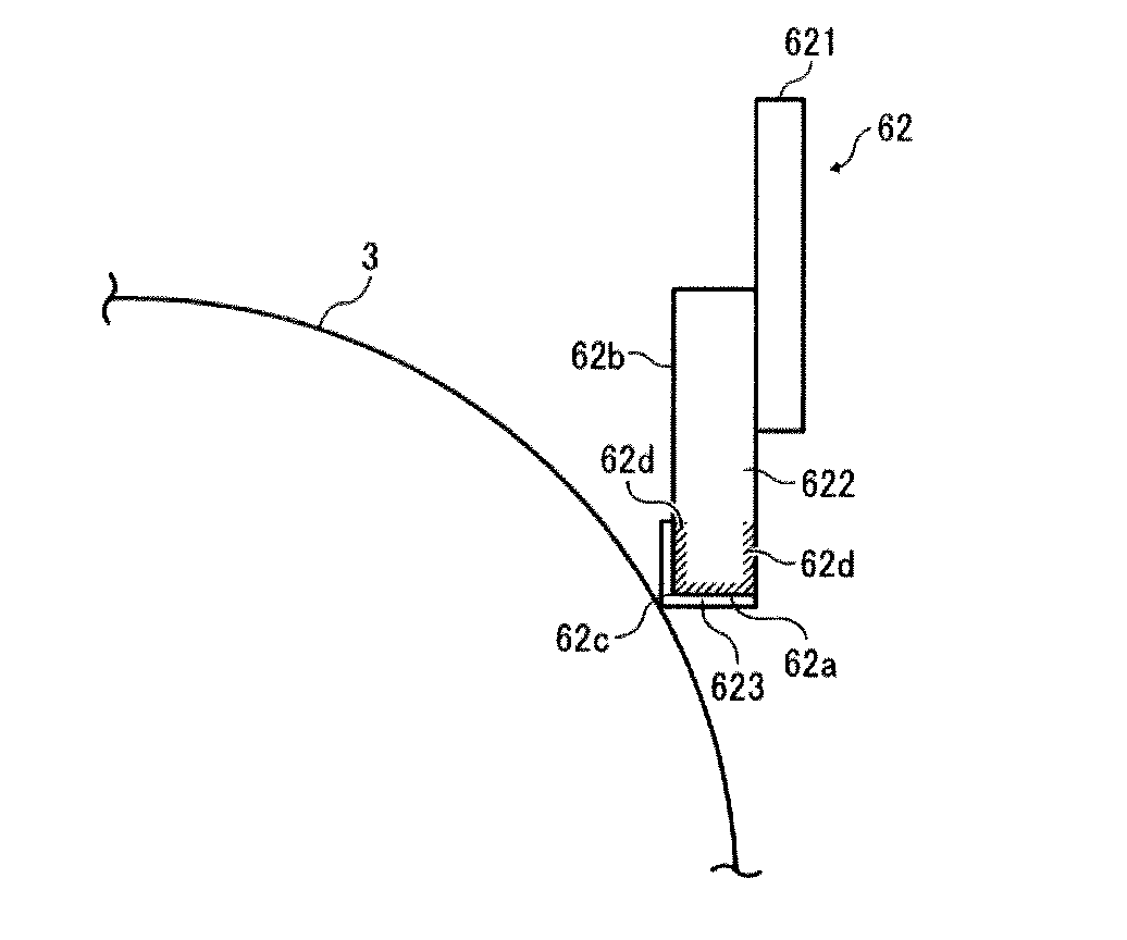
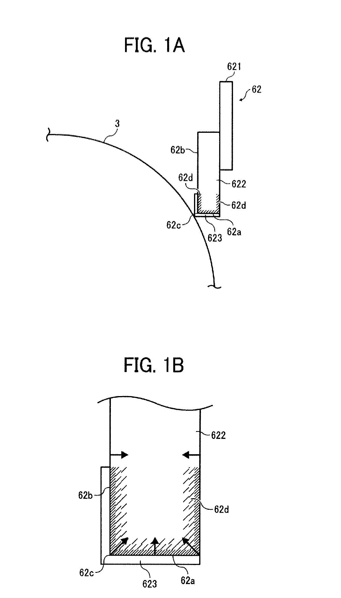
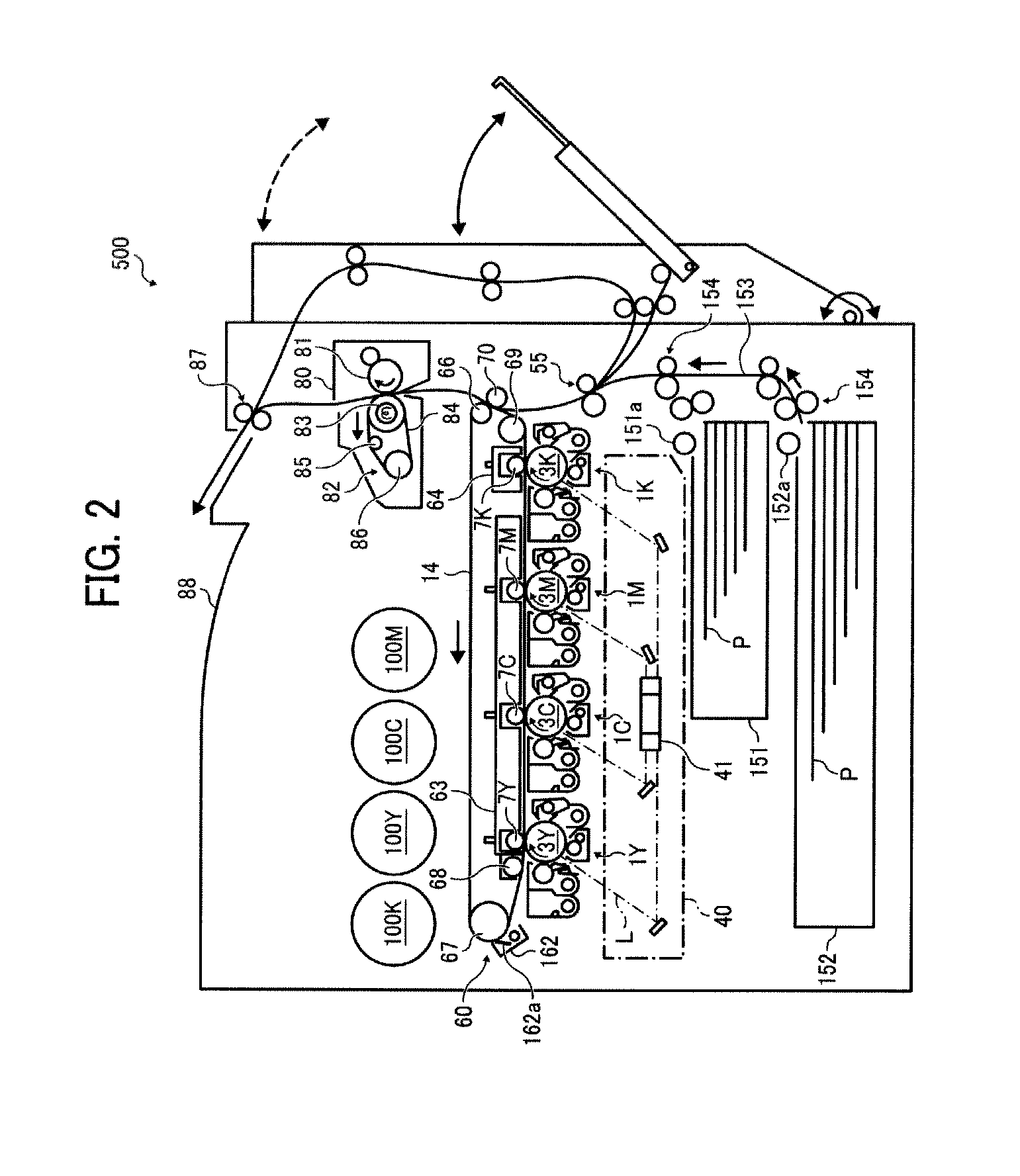
This patent describes an image forming apparatus that uses a cleaning blade with an elastic blade and a harder edge line. The edge line helps the blade follow the path of the photoreceptor to keep it clean and prevents the photoreceptor from being damaged by eccentric abrasion. The technical effect is that the apparatus can produce high-quality images consistently and efficiently.

Problems solved by technology

However, polymerization toner has such a drawback as not to be easily removed from a photoreceptor by a cleaning blade.
However, as disclosed in Japanese published unexamined application No.
In this regard, the thus everted tip has a restoring force, and therefore the tip tends to vibrate, resulting in generation of fluttering sounds.
However, even when the above-mentioned cleaning blades are used, occurrence of the above-mentioned problems is hardly prevented if images having a high image area proportion (such as image having large solid images) are continuously produced (i.e., if the amount of residual toner on a photoreceptor to be removed by the cleaning blade is large).
Specifically, since the blade has a cover layer on the tip thereof or includes a crosslinked material in a surface portion thereof in the longitudinal direction thereof, the elastic property of the rubber of the blade tends to deteriorate.
In addition, when images having high image area proportions are continuously produced and a large amount of residual toner is present on the surface of the photoreceptor, the large amount of toner is collected at the tip of the blade by being blocked by the blade.
In this case, the residual toner at the tip of the blade tends to pass through a relatively large gap formed between a portion of the blade and the surface of the photoreceptor, which are contacted with each other at a relatively low pressure due to eccentricity of the photoreceptor or waving of the surface thereof, resulting in occurrence of the above-mentioned abnormal image problem.
Such an elastic blade deteriorates in elasticity and followability to eccentric variation of a photoreceptor, resulting in poor cleanability.
Then, when the surface layer thickness is made thicker, the elastic blade deteriorates in elasticity and followability to eccentric variation of a photoreceptor, resulting in poor cleanability.
However, when a large amount of the ultraviolet crosslinkable material is impregnated, the impregnated part is formed too hard and deep, resulting in deterioration of elasticity of the elastic blade.
Therefore, the edge line of the cleaning blade deteriorates in followability to the surface of a photoreceptor, resulting in poor cleanability.
In addition, when a cleaning blade having an edge line harder than the elastic blade is used, the surface of a photoreceptor is abraded earlier than when only the elastic blade is used, resulting in deterioration of image quality such as background fouling.
Hard layers contact each other with friction, abrasion of the cleaning blade or the photoreceptor is accelerated as time passes, resulting in poor cleanability.

Method used


Image

  • Image forming apparatus and process cartridge
  • Image forming apparatus and process cartridge
  • Image forming apparatus and process cartridge

Examples


examples

[0207]Having generally described this invention, further understanding can be obtained by reference to certain specific examples which are provided herein for the purpose of illustration only and are not intended to be limiting. In the descriptions in the following examples, the numbers represent weight ratios in parts, unless otherwise specified.

[0208]Cleaning blades 1 to 29 were prepared using the following elastic blades 622; the substrate and the acrylic and / or methacrylic resin mixed layer 62d, the impregnation time and the thickness; and the acrylic and / or methacrylic resin surface layer 623 and the thickness.

(Elastic Blade)

[0209]The following materials were used for the elastic blade 622.

ResilienceHardnesscoefficientMaterial(°) at 25° C.(%)at 25° C.ManufacturerUrethane rubber 16646Bando ChemicalIndustries, Ltd.Urethane rubber 27050Toyo Tire & RubberCo., Ltd.Urethane rubber 37231Toyo Tire & RubberCo., Ltd.Urethane rubber 47521Toyo Tire & RubberCo., Ltd.Urethane rubber 57719Syn...


PUM


Abstract

An image forming apparatus including at least a photoreceptor; and a cleaning blade formed of a strip-shaped elastic blade to contact an edge line to the surface of the photoreceptor, wherein the photoreceptor includes a surface layer comprising a particulate material, and the edge line of the cleaning blade includes a substrate of the elastic blade; a mixed layer having a thickness not less than 1.0 μm, formed of the substrate and at least one of an acrylic resin and a methacrylic resin, located at the surface of the substrate; and a surface layer having a thickness not less than 0.1 μm, formed of at least one of an acrylic resin and a methacrylic resin, located on the surface of the substrate.

Description

CROSS-REFERENCE TO RELATED APPLICATIONS[0001]This patent application is based on and claims priority pursuant to 35 U.S.C. §119 to Japanese Patent Application No. 2012-055986, filed on Mar. 13, 2012, in the Japan Patent Office, the entire disclosure of which is hereby incorporated by reference herein.BACKGROUND OF THE INVENTION[0002]1. Field of the Invention[0003]The present invention relates to an image forming apparatus such as copiers, printers, facsimiles and direct digital platemakers, and a process cartridge used therein.[0004]2. Description of the Related Art[0005]In electrophotographic image forming apparatuses, residual toner remaining on the surface of a photoreceptor even after a toner image thereon is transferred onto a recording material or an intermediate transfer medium is removed therefrom using a cleaner.[0006]Strip-shaped cleaning blades made of an elastic material such as polyurethane rubbers are typically used for such a cleaner because of having advantages such ...

Claims


Application Information

Patent Timeline
IPC IPC(8): G03G21/00G03G21/18
CPCG03G21/1814G03G21/0017
Inventor IKUNO, HIROSHISAKON, YOHTAOHMORI, MASAHIROEGAWA, KAZUHIROTOSHINE, TETSUYA
Owner RICOH KK
Learn More