
Dual Frequency Damper for an Aircraft

a technology for dampers and aircraft, applied in the direction of shock absorbers, machine supports, transportation and packaging, etc., can solve the problems of affecting the life of structural components, affecting the rotorcraft,

Active Publication Date: 2013-09-19
TEXTRON INNOVATIONS
View PDF8 Cites 8 Cited by
  • Summary
  • Abstract
  • Description
  • Claims
  • Application Information

AI Technical Summary

Benefits of technology

The present patent is about a damper for a rotorcraft that helps to compensate for the acceleration and deceleration of each rotor blade about a rotor blade hub. The damper is designed to treat lead / lag oscillatory forces that can negatively affect the rotorcraft. The technical effect of this patent is to provide a better damper that can better treat these forces and improve the life and safety of the rotorcraft.

Problems solved by technology

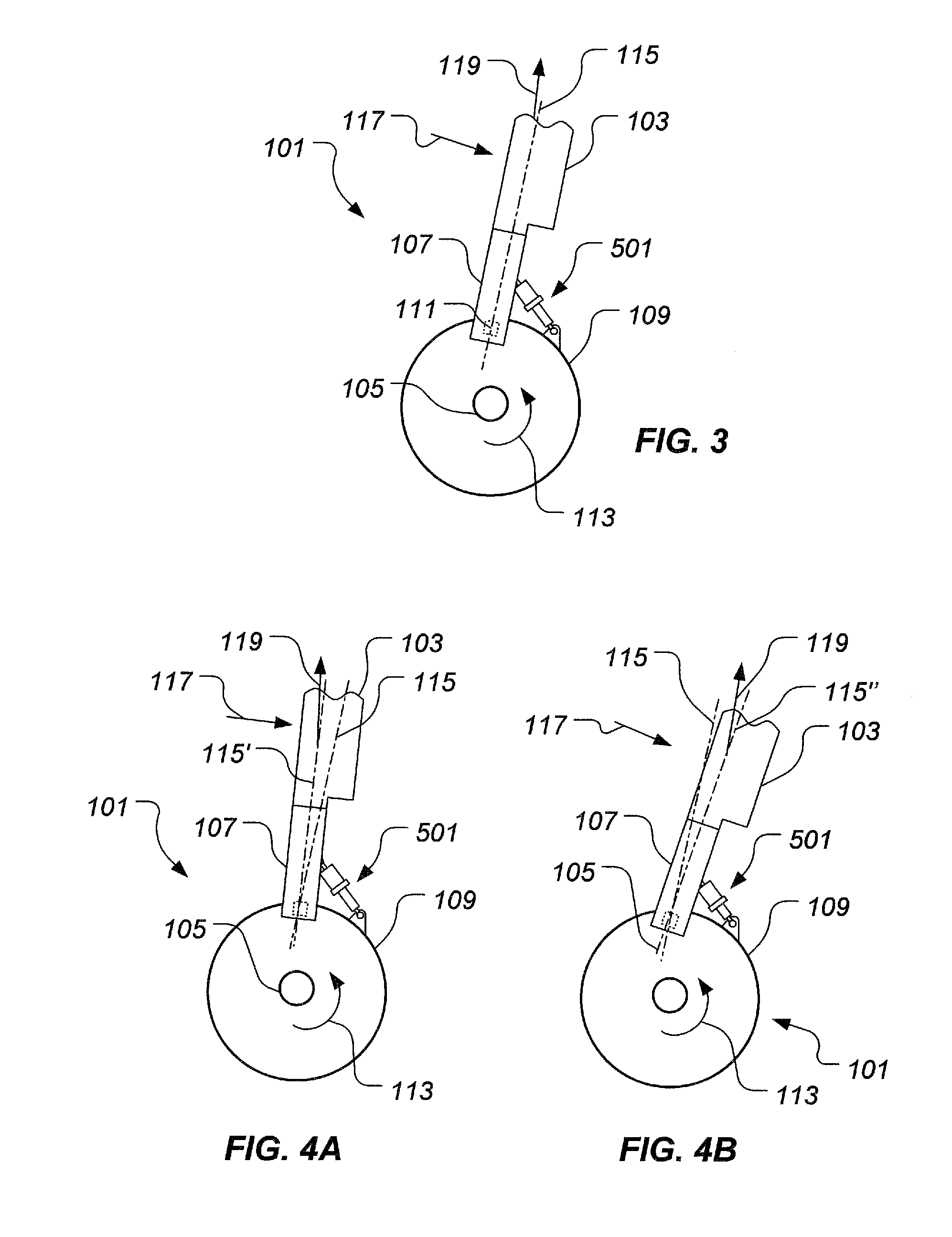
During forward flight of the rotorcraft, unequal drag forces on the advancing and retreating rotor blade positions typically cause oscillating forces that if left untreated, can negatively affect the rotorcraft.
For example, untreated lead / lag oscillating forces can severely limit the life of structural components through fatigue.
Furthermore, untreated lead / lag oscillating forces have been known to cause catastrophic results in a “ground resonance” phenomenon in which the oscillation frequency is similar to the resonant frequency of the aircraft on its landing gear.

Method used


Image

  • Dual Frequency Damper for an Aircraft
  • Dual Frequency Damper for an Aircraft
  • Dual Frequency Damper for an Aircraft

Examples


Embodiment Construction

[0018]The particular embodiments disclosed above are illustrative only, as the application may be modified and practiced in different but equivalent manners apparent to those skilled in the art having the benefit of the teachings herein. Furthermore, no limitations are intended to the details of construction or design herein shown, other than as described in the claims below. It is therefore evident that the particular embodiments disclosed above may be altered or modified and all such variations are considered within the scope and spirit of the application. Accordingly, the protection sought herein is as set forth in the claims below. It is apparent that a system with significant advantages has been described and illustrated. Although the system of the present application is shown in a limited number of forms, it is not limited to just these forms, but is amenable to various changes and modifications without departing from the spirit thereof.

[0019]In the specification, reference ma...


PUM


Abstract

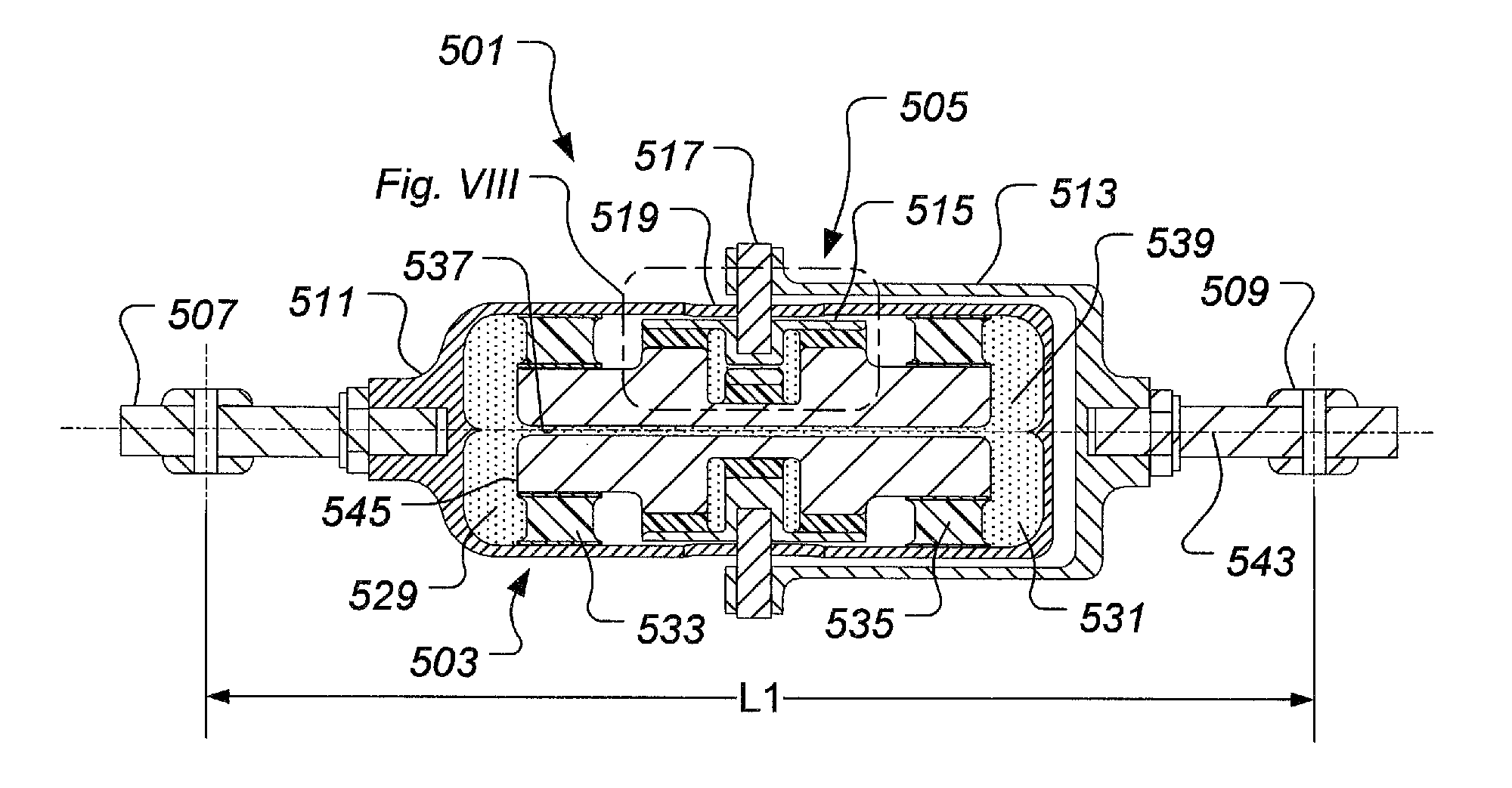
A dual frequency damper includes a liquid inertia vibration eliminator (LIVE) portion and a fluid damper portion. LIVE portion and fluid damper portion operate in series and function so that dual frequency damper is optimized in both stiffness and damping at multiple frequencies. LIVE portion acts as a frequency dependent switch to selectively cause low frequency oscillatory forces to be treated primarily by the high spring rate and high damping rate characteristics of the fluid damper portion, and also to select high frequency oscillatory forces to be primarily treated by the low spring rate and low damping rate characteristics of the LIVE unit portion.

Description

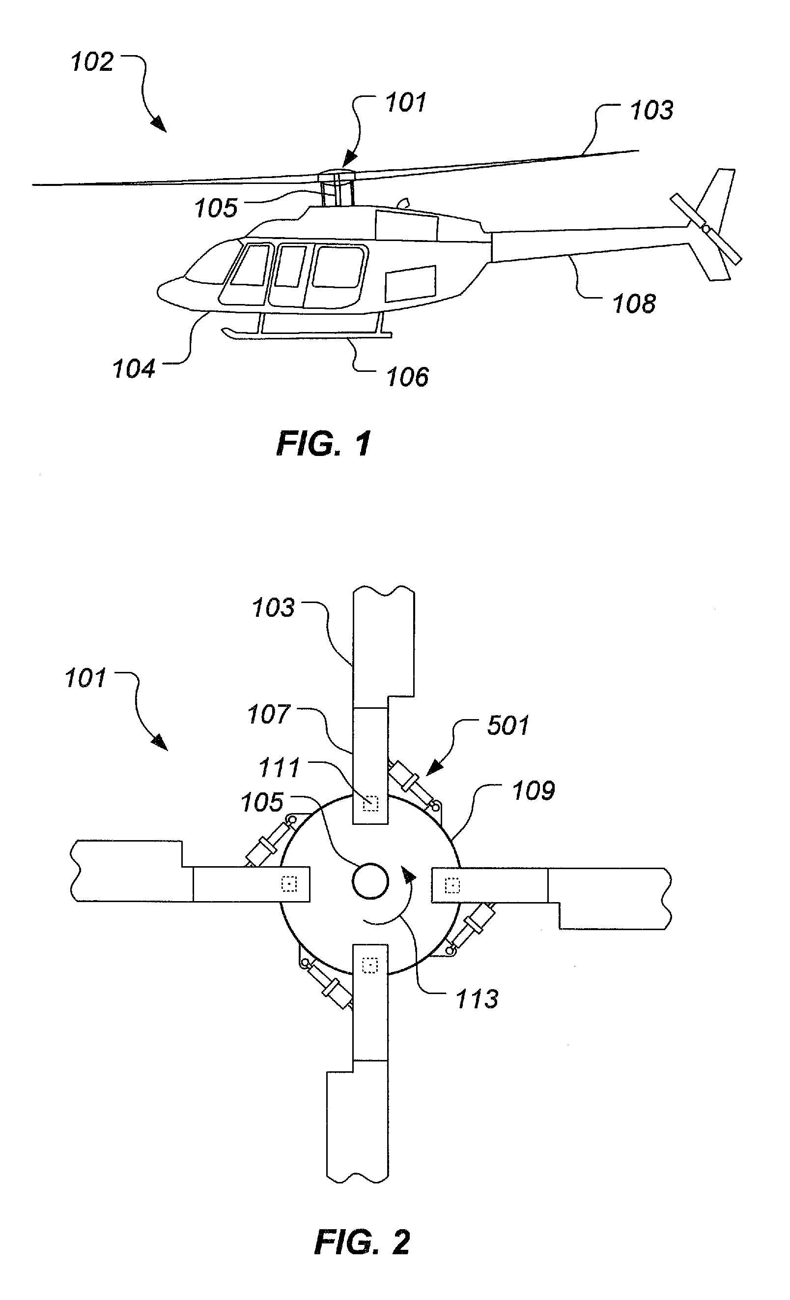
BACKGROUND[0001]Technical Field[0002]The system of the present application relates to a damper for an aircraft. In particular, the system of the present application relates to a lead / lag damper for a rotorcraft. The damper is particularly well suited for use in the field of rotary wing aircraft; however, other types of aircraft can implement the damper as well. It should be appreciated that even though the damper is illustrated herein with regard to an aircraft, one ordinary skill in the art with benefit of this disclosure will recognize that the damper can be implemented in applications other than an aircraft.[0003]Description of Related Art[0004]Certain conventional rotorcraft can have multi-bladed rotor hub configurations that require lead / lag dampers to compensate for the acceleration and deceleration of each rotor blade about a rotor blade hinge axis. During forward flight of the rotorcraft, unequal drag forces on the advancing and retreating rotor blade positions typically cau...

Claims


Application Information

Patent Timeline
IPC IPC(8): B64C27/51F16F13/08
CPCB64C27/51
Inventor BOSWORTH, JEFFREYYUCE, MITHATSTAMPS, FRANK B.SMITH, MICHAEL R.
Owner TEXTRON INNOVATIONS
Learn More