Vibration suppression apparatus and vibration suppression method
a technology of vibration suppression apparatus and vibration suppression method, which is applied in the direction of mechanical apparatus, other domestic objects, machine supports, etc., can solve the problems of reducing the accuracy and resolution (transfer) performance of overlays, affecting the stability of elastic supports, etc., to achieve the effect of suppressing vibration propagation
- Summary
- Abstract
- Description
- Claims
- Application Information
AI Technical Summary
Benefits of technology
Problems solved by technology
Method used
Image
Examples
first embodiment
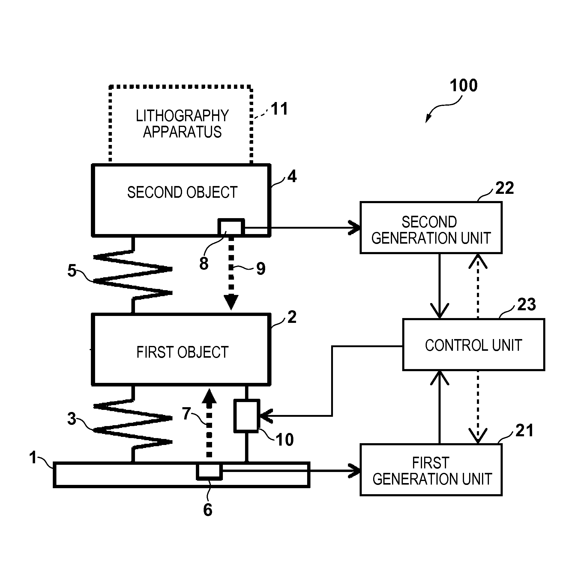
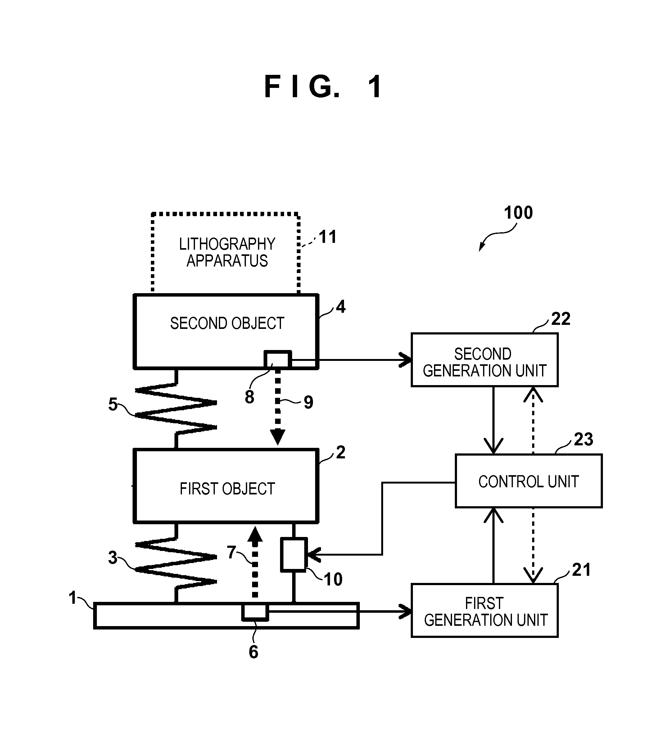
[0019]A vibration suppression apparatus 100 according to the first embodiment of the present invention will be described with reference to FIG. 1. The vibration suppression apparatus generally suppresses vibrations in the vertical direction (Z direction) and the horizontal direction (X and Y directions). Vibration suppression in the vertical direction (Z direction) will be explained for the vibration suppression apparatus 100 according to the first embodiment. The vibration suppression apparatus 100 according to the first embodiment includes a base 1, first object 2, second object 4, and driving unit 10. The vibration suppression apparatus 100 also includes a first measurement unit 6, second measurement unit 8, first generation unit 21, second generation unit 22, and control unit 23.
[0020]The base 1 is fixed to a foundation (floor) in a place where a lithography apparatus 11 such as a drawing apparatus or exposure apparatus is installed. The first object 2 is elastically supported o...
second embodiment
[0037]A vibration suppression apparatus 200 according to the second embodiment of the present invention will be described with reference to FIG. 4. Unlike the vibration suppression apparatus 100 according to the first embodiment, the vibration suppression apparatus 200 according to the second embodiment does not include the first measurement unit 6, but further includes a pedestal 12, third measurement unit 13, and adder 17. The pedestal 12 is fixed to a base 1, and has an inverted L shape formed from a post 12a and top plate 12b. The third measurement unit 13 is arranged in the top plate 12b, and measures a relative distance 14 (to be referred to as a third relative distance 14 hereinafter) between the top plate 12b and a second object 4. The adder 17 calculates the relative distance between the base 1 and a first object 2 by subtracting the third relative distance 14 and a second relative distance 9 from the distance between the top plate 12b and the base 1 (the thicknesses of the...
third embodiment
[0039]A vibration suppression apparatus 300 according to the third embodiment of the present invention will be described with reference to FIG. 5. Unlike the vibration suppression apparatus 100 according to the first embodiment, the vibration suppression apparatus 300 according to the third embodiment further includes a vibration suppression system 30, and uses a vibration suppression apparatus 100 as the measurement reference of the vibration suppression system 30. The vibration suppression system 30 is formed from a third object 18, pedestal 12, fixing table 19, air spring 20, second driving unit 24, and second control unit 25. The vibration suppression apparatus 300 according to the third embodiment does not include the first measurement unit 6, but includes a third measurement unit 13.
[0040]The third object 18 is elastically supported by the air spring 20 on the pedestal 12 fixed to a base 1. The fixing table 19 is arranged beside the air spring 20, which are interposed between ...
PUM
 Abstract
Description
Claims
Application Information
 - R&D
- Intellectual Property
- Life Sciences
- Materials
- Tech Scout
- Unparalleled Data Quality
- Higher Quality Content
- 60% Fewer Hallucinations
Browse by: Latest US Patents, China's latest patents, Technical Efficacy Thesaurus, Application Domain, Technology Topic, Popular Technical Reports.
© 2025 PatSnap. All rights reserved.Legal|Privacy policy|Modern Slavery Act Transparency Statement|Sitemap|About US| Contact US: help@patsnap.com


