
Fixing structure of wiring and image forming apparatus

Inactive Publication Date: 2007-07-19
KYOCERA DOCUMENT SOLUTIONS INC
View PDF22 Cites 1 Cited by
  • Summary
  • Abstract
  • Description
  • Claims
  • Application Information

AI Technical Summary

Benefits of technology

[0011] Therefore, in the fixing structure of wiring as structured above, the drive member and the wire come into contact each other by interposing the wire in a gap formed between the drive member and the supporting member, and therefore, the drive member is elastically supported by elastic function of the coating member of the wire. This elastic function suppresses the vibration transmission of the drive member. Additionally, the wobble between the drive member and the supporting member mounted in the electronic device is also dissolved with an infill of the wire as the elastic body.
[0013] Interposing the wire in between the even surfaces indicates the pressure provided to the wire being dispersed, and the possibility of deformation or damage of the wire becomes low, compared to the case when the wire is interposed between lines, points or edges.
[0016] When a drive member driven with vibration is provided in an electronic device, the drive member may be supported by a supporting member that supports the drive member by engaging therewith. In such case, the present invention can realize alleviation of the wobble generated by the vibration at the operating time of the drive member, as well as reduction of unwanted sound and vibration caused by the above wobble, and provide a fixing structure of wiring capable of fixing the wire inexpensively without additional and specific materials for wiring.

Problems solved by technology

This specific duct has a structure, which, by setting a wire thereon, does not allow the wire set on the specific duct to slide off.
However, the image forming apparatus disclosed in the prior art 1 had a problem of additional cost, since additional and specific materials were required.
However, when fixing only by engagement as noted above, the wobble may be generated by the vibration at the operating time of the drive member because of the size tolerance at the engaging part between the drive member and the supporting member, and additionally, unwanted sound as well as vibration occurred by such wobble has been a problem.

Method used


Image

  • Fixing structure of wiring and image forming apparatus
  • Fixing structure of wiring and image forming apparatus
  • Fixing structure of wiring and image forming apparatus

Examples


Embodiment Construction

[0022] With embodiments of the present invention described hereinafter with reference to the accompanying drawings, it is to be understood that the invention is not limited to those precise embodiments, and that various changes and modifications may be effected therein by one skilled in the art without departing from the scope or spirit of the invention as defined in the appended claims.

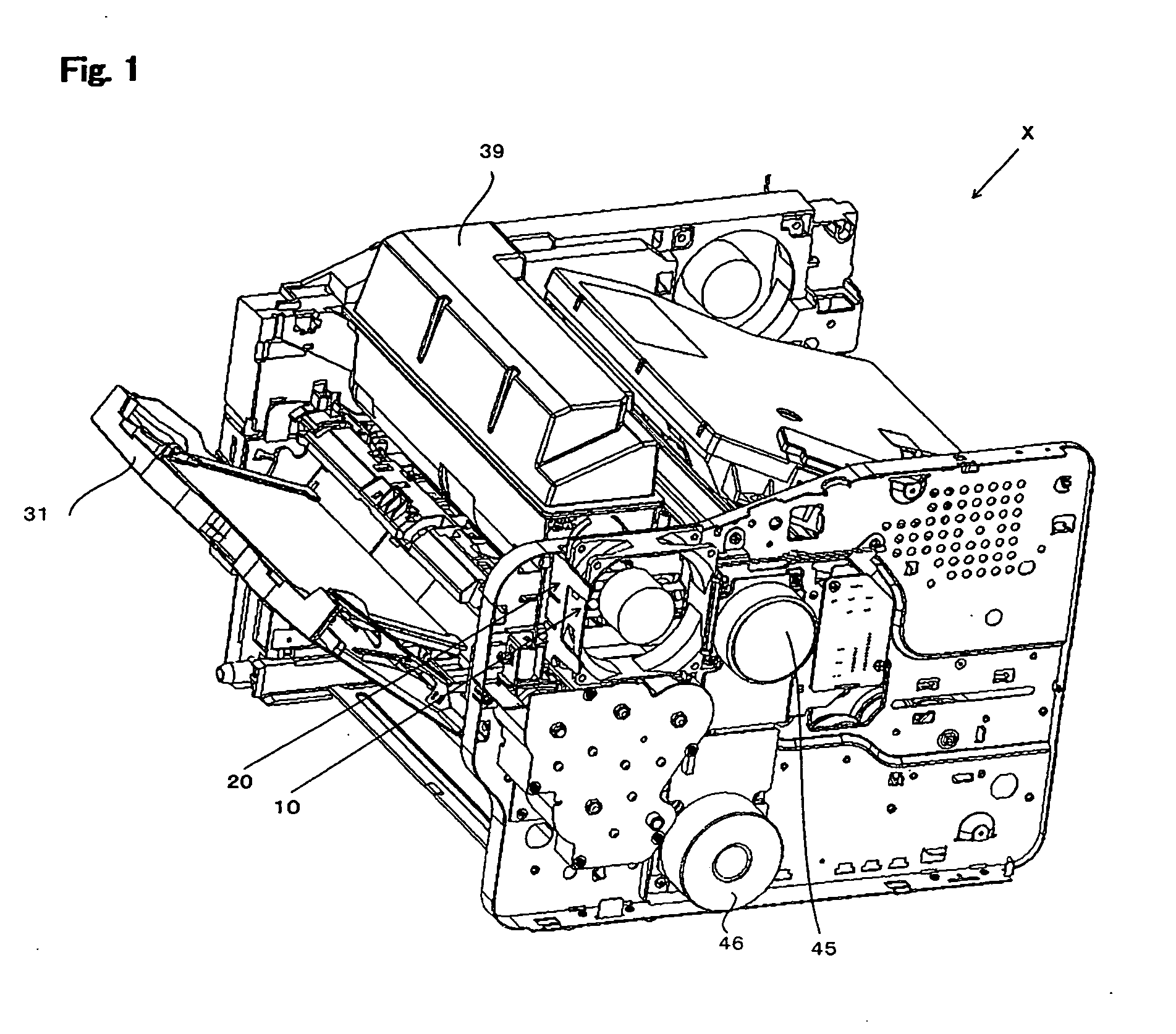
[0023] Referring now to FIGS. 1, 2, and 3, the schematic structure of an image forming apparatus X employing a fixing structure of wiring according to the present invention is briefly described in the following. In FIG. 1 and 3 (b), a fan blade 14B is abbreviated for purpose of explanation.

[0024] As indicated in FIG. 2, Image forming apparatus X is roughly comprised of a paper feeder K, an image forming unit G, and a fixing member T.

[0025] Furthermore, as indicated in FIG. 3, provided in the side surface of the main body of Image forming apparatus X, near after-mentioned developing member Z provid...


PUM


Abstract

The object of this invention is, in an electronic device provided with a supporting member that supports a drive member driven with vibration by engaging therewith, to provide the fixing structure of wiring that realizes the following: alleviation of the wobble generated by the vibration at the operating time of the drive member, reduction of unwanted sound and vibration caused by the above wobble, and inexpensive fixing of a wire without additional and specific members for wiring. This invention is constituted as a fixing structure of wiring for fixing a wire wired in an electronic device, wherein a drive member driven with vibration and a supporting member for supporting the drive member by engaging therewith are provided in the electronic device, and wherein the wire is fixed by being interposed in a gap formed between the drive member and the supporting member.

Description

BACKGROUND OF THE INVENTION [0001] 1. Field of the Invention [0002] The present invention relates to a fixing structure of wiring for fixing a wire wired in an electronic device and an image forming apparatus comprised thereof, and particularly, relates to a fixing structure of wiring, which can fix a wire without additional and specific components, and an image forming apparatus comprised thereof. [0003] 2. Description of the Related Art [0004] Conventionally, as a structure for fixing a wire wired in an electronic device in a proper position, it has been general to provide specific and additional materials for fixing a wire. [0005] The image forming apparatus disclosed in Japanese Unexamined Patent Publication No. 2003-162189 is provided with a specific duct of semicircular and tubular shape in a duct mounted with an exhaust fan. This specific duct has a structure, which, by setting a wire thereon, does not allow the wire set on the specific duct to slide off. [0006] However, the ...

Claims


Application Information

Patent Timeline
IPC IPC(8): H05K7/20
CPCH05K7/20172
Inventor MIZUGUCHI, KEISUKE
Owner KYOCERA DOCUMENT SOLUTIONS INC
Learn More