
Optical feed-forward equalizer for MIMO signal processing

a technology of mimo signal processing and equalizer, applied in the field of optical communication equipment, can solve the problems of affecting the transmission performance of optical transport links, requiring relatively high power to operate, and being relatively expensive to design and/or fabricate, so as to reduce the signal processing load and/or signal processing requirements

Active Publication Date: 2013-09-12
WSOU INVESTMENTS LLC
View PDF17 Cites 28 Cited by
  • Summary
  • Abstract
  • Description
  • Claims
  • Application Information

AI Technical Summary

Benefits of technology

The patent describes an optical feed-forward equalizer that improves the processing of optical signals by reducing the effects of chromatic dispersion, polarization-mode dispersion, and spatial-mode mixing / crosstalk. The device is part of a host optical receiver and helps to simplify the signal processing required. Additionally, the patent describes a controller that causes the device to display patterns in a way that further compensates for dispersion. The technical effect of this patent is to improve the quality of optical signal processing and reduce the processing requirements on the receiver's electrical DSP.

Problems solved by technology

At these rates, the effects of chromatic dispersion (CD) and polarization-mode dispersion (PMD) may significantly degrade the transmission performance of optical transport links.
This electrical digital signal processing is typically implemented using a customized ASIC, which can be relatively expensive to design and / or fabricate.
In addition, such an ASIC typically requires relatively high power to operate, with the consumed power being approximately proportional to the operative baud rate squared.
The optical MIMO methods that exploit the inherently high transmission capacity of multipath (e.g., multimode and / or multi-core) optical fibers tend to further increase the complexity of digital signal processing at the receiver, e.g., because the corresponding ASIC may be additionally configured to deal with the effects of spatial-mode mixing and crosstalk in the corresponding multipath optical transport link.
By some estimates, the complexity of an ASIC configured to process MIMO signals might be about one hundred times higher than that of an ASIC that does not implement MIMO processing.
As a result, practical implementation and operation of an electrical digital signal processor (DSP) configured to handle the effects of CD, PMD, and spatial-mode mixing / crosstalk in an optical MIMO system might be too expensive for commercial applications.

Method used


Image

  • Optical feed-forward equalizer for MIMO signal processing
  • Optical feed-forward equalizer for MIMO signal processing
  • Optical feed-forward equalizer for MIMO signal processing

Examples


Embodiment Construction

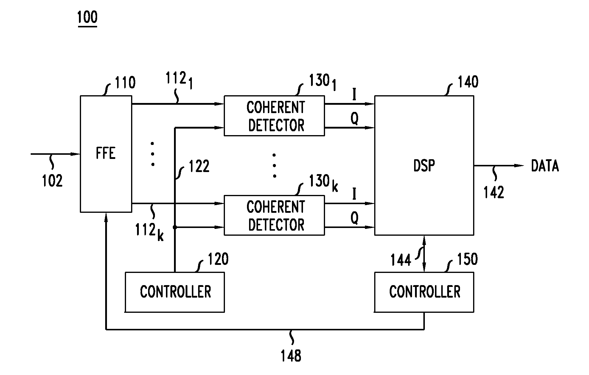
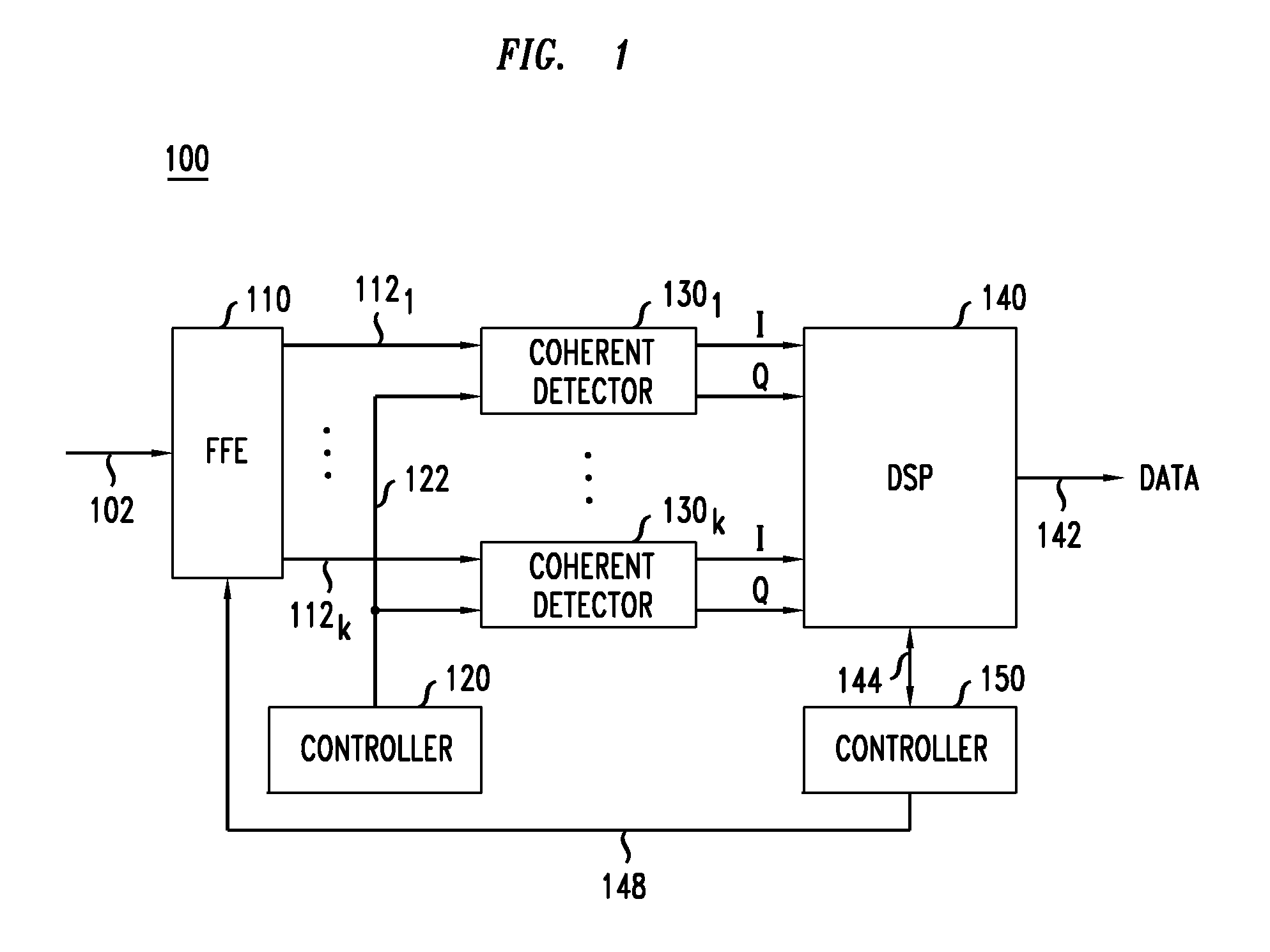
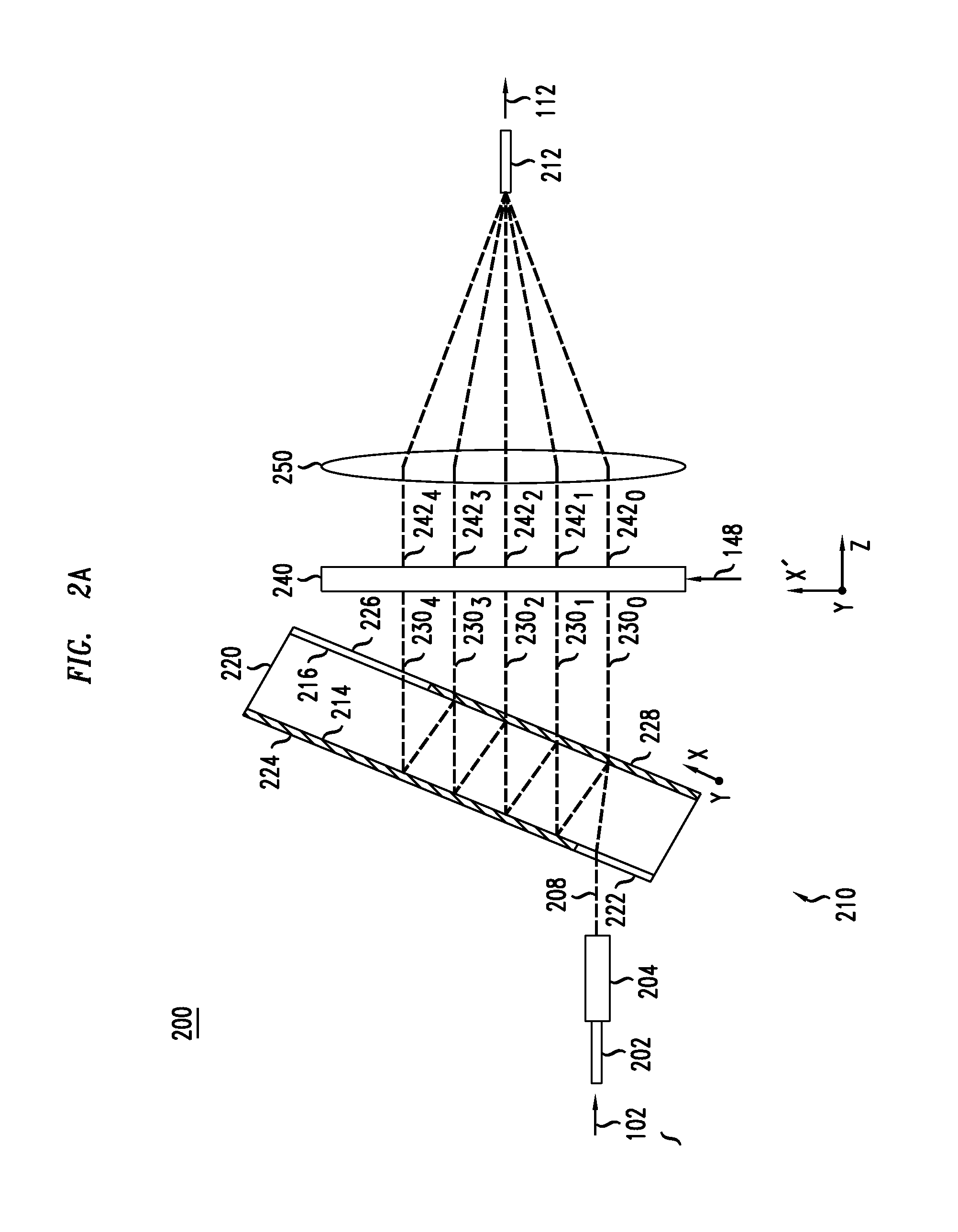
[0008]At least some of the above-indicated problems are addressed by various embodiments of an optical feed-forward equalizer disclosed herein. In one embodiment, the optical feed-forward equalizer is part of the host optical receiver that enables the latter to perform at least some of the desired signal processing in the optical domain, e.g., prior to coherently detecting and digitizing the received optical signal(s). The optical signal processing implemented in the optical feed-forward equalizer can be used, e.g., to at least partially compensate the adverse effects of chromatic dispersion, polarization-mode dispersion, and / or spatial-mode mixing / crosstalk imposed on the received optical signal(s) by the optical transport link. This reduces the signal-processing load of and / or the signal-processing requirements to the receiver's electrical DSP.

[0009]According to one embodiment, provided is an apparatus comprising an optical feed-forward equalizer configured to be coupled between a...


PUM


Abstract

A feed-forward equalizer can be used in the host optical receiver to perform at least some of the desired signal processing in the optical domain, e.g., prior to coherently detecting and digitizing the received optical signal(s). In some embodiments, the signal processing implemented in the feed-forward equalizer can at least partially compensate the adverse effects of chromatic dispersion, polarization-mode dispersion, and / or spatial-mode mixing / crosstalk imparted on the received optical signal(s) in the optical transport link. This reduces the signal-processing load of and the signal-processing requirements to the receiver's electrical DSP.

Description

CROSS-REFERENCE TO RELATED APPLICATIONS[0001]This application claims priority from U.S. Provisional Patent Application No. 61 / 608,246, filed on Mar. 8, 2012, and entitled “OPTICAL FEED-FORWARD EQUALIZER, SUCH AS FOR AN OPTICAL RECEIVER.” This provisional patent application is incorporated herein by reference in its entirety.BACKGROUND[0002]1. Field of the Invention[0003]The present invention relates to optical communication equipment and, more specifically but not exclusively, to an optical feed-forward equalizer that can be used in MIMO (multiple input, multiple output) signal processing.[0004]2. Description of the Related Art[0005]This section introduces aspects that may help facilitate a better understanding of the invention(s). Accordingly, the statements of this section are to be read in this light and are not to be understood as admissions about what is in the prior art or what is not in the prior art.[0006]The next-generation of optical communication systems is being designed...

Claims


Application Information

Patent Timeline
Patent Type & Authority Applications(United States)
IPC IPC(8): H04B10/69
CPCH04B10/615G02B6/29358G02B6/29395H04B10/6971
Inventor RYF, ROLAND
Owner WSOU INVESTMENTS LLC
Learn More